
How to Use TI Launchpad MSP430G2: Examples, Pinouts, and Specs
 Design with TI Launchpad MSP430G2 in Cirkit Designer
Introduction
The TI Launchpad MSP430G2 is a low-cost development platform designed for Texas Instruments' MSP430 microcontrollers. It provides a versatile and user-friendly environment for rapid prototyping and development. The platform features a range of integrated peripherals, including onboard LEDs, push buttons, and a USB interface for programming and debugging. Its compact design and compatibility with Energia (an Arduino-like IDE) make it an excellent choice for both beginners and experienced developers.
Explore Projects Built with TI Launchpad MSP430G2
 Open Project in Cirkit Designer
 Open Project in Cirkit Designer
 Open Project in Cirkit Designer
 Open Project in Cirkit Designer
Explore Projects Built with TI Launchpad MSP430G2
Open Project in Cirkit DesignerOpen Project in Cirkit DesignerOpen Project in Cirkit DesignerOpen Project in Cirkit DesignerCommon Applications and Use Cases
- Embedded systems prototyping
- Low-power IoT devices
- Sensor interfacing and data acquisition
- Educational projects and microcontroller learning
- Home automation and control systems
Technical Specifications
The TI Launchpad MSP430G2 is built to support a variety of MSP430 microcontrollers, offering flexibility and scalability for different applications. Below are the key technical details:
General Specifications
| Feature | Description |
|---|---|
| Microcontroller Support | MSP430G2xx series (e.g., MSP430G2553, MSP430G2452) |
| Operating Voltage | 3.3V (regulated from USB power) |
| Clock Speed | Up to 16 MHz (depending on the MCU) |
| Debugging Interface | USB-based MSP430 Debug Interface (eZ-FET Lite) |
| Programming Interface | USB (via onboard emulator) |
| GPIO Pins | Up to 16 (depending on the MCU) |
| Onboard Peripherals | 2 LEDs (red and green), 1 push button |
| Power Supply | USB-powered or external supply (via headers) |
Pin Configuration and Descriptions
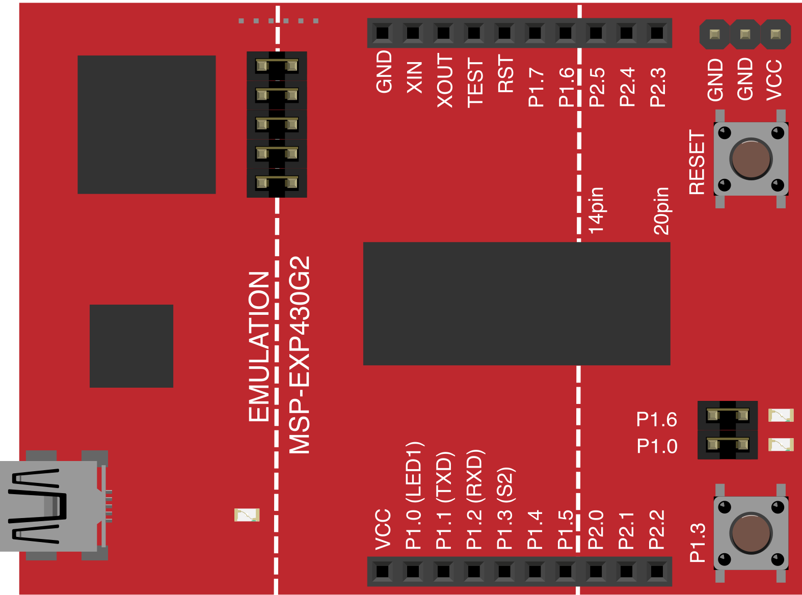
The Launchpad features a 20-pin DIP socket for the MSP430 microcontroller and breakout headers for easy access to GPIO pins. Below is the pinout for the MSP430G2553 microcontroller:
| Pin Number | Pin Name | Description |
|---|---|---|
| 1 | P1.0 | GPIO, ADC input, or Timer output |
| 2 | P1.1 | GPIO, ADC input, or UART RX |
| 3 | P1.2 | GPIO, ADC input, or UART TX |
| 4 | P1.3 | GPIO or ADC input |
| 5 | P1.4 | GPIO or Timer output |
| 6 | P1.5 | GPIO or Timer output |
| 7 | P2.0 | GPIO or Timer output |
| 8 | P2.1 | GPIO or Timer output |
| 9 | P2.2 | GPIO or Timer output |
| 10 | P2.3 | GPIO or Timer output |
| 11 | P2.4 | GPIO or Timer output |
| 12 | P2.5 | GPIO or Timer output |
| 13 | P2.6 | GPIO or Timer output |
| 14 | P2.7 | GPIO or Timer output |
| 15 | VCC | Power supply (3.3V) |
| 16 | GND | Ground |
| 17 | RST | Reset pin |
| 18 | TEST | Test pin for debugging |
| 19 | XIN | External crystal input |
| 20 | XOUT | External crystal output |
Usage Instructions
How to Use the TI Launchpad MSP430G2 in a Circuit
Install the Required Software:
- Download and install Code Composer Studio (CCS) or Energia IDE for programming.
- Install the necessary drivers for the MSP430 Launchpad.
Connect the Launchpad:
- Plug the Launchpad into your computer using a USB cable.
- Ensure the onboard LEDs light up, indicating power and proper connection.
Write and Upload Code:
- Open the IDE (CCS or Energia) and select the appropriate microcontroller model.
- Write your code and upload it to the Launchpad using the "Upload" or "Debug" button.
Connect External Components:
- Use the breakout headers to connect sensors, actuators, or other peripherals.
- Ensure proper voltage levels and pin configurations.
Power the Circuit:
- The Launchpad can be powered via USB or an external power source connected to the VCC and GND pins.
Important Considerations and Best Practices
- Voltage Levels: Ensure all connected components operate at 3.3V to avoid damaging the microcontroller.
- Pin Multiplexing: Many pins have multiple functions (e.g., GPIO, ADC, UART). Configure them appropriately in your code.
- Debouncing: When using the onboard push button, implement software debouncing to avoid erratic behavior.
- External Crystals: For precise timing applications, connect an external crystal oscillator to the XIN and XOUT pins.
Example Code for Blinking an LED
Below is an example code snippet for blinking the onboard red LED (P1.0) using Energia:
// Blink the onboard red LED on the TI Launchpad MSP430G2
// The red LED is connected to pin P1.0

void setup() {
  pinMode(RED_LED, OUTPUT); // Set P1.0 (RED_LED) as an output
}

void loop() {
  digitalWrite(RED_LED, HIGH); // Turn the LED on
  delay(500);                  // Wait for 500 milliseconds
  digitalWrite(RED_LED, LOW);  // Turn the LED off
  delay(500);                  // Wait for 500 milliseconds
}
Troubleshooting and FAQs
Common Issues and Solutions
The Launchpad is not detected by the computer:
- Ensure the USB cable is properly connected and functional.
- Install or update the MSP430 drivers from Texas Instruments' website.
Code does not upload to the microcontroller:
- Verify that the correct microcontroller model is selected in the IDE.
- Check for loose connections or damaged USB ports.
Onboard LEDs do not light up:
- Confirm that the Launchpad is receiving power via USB or an external source.
- Check for short circuits or damaged components.
External components are not working as expected:
- Double-check the wiring and pin configurations.
- Ensure the components are compatible with 3.3V logic levels.
FAQs
Q: Can I use the TI Launchpad MSP430G2 with Arduino libraries?
A: Yes, you can use the Energia IDE, which is based on Arduino, to program the Launchpad with Arduino-like syntax and libraries.
Q: What is the maximum current output of the GPIO pins?
A: Each GPIO pin can source or sink up to 6 mA. Exceeding this limit may damage the microcontroller.
Q: Can I use an external power supply instead of USB?
A: Yes, you can power the Launchpad using an external 3.3V supply connected to the VCC and GND pins.
Q: How do I reset the microcontroller?
A: Press the onboard reset button or pull the RST pin low momentarily.
By following this documentation, you can effectively utilize the TI Launchpad MSP430G2 for your embedded system projects.