
How to Use Potentiometer: Examples, Pinouts, and Specs
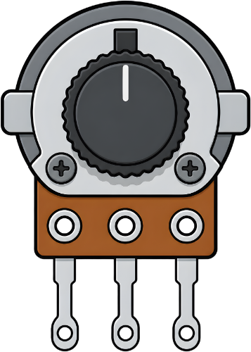
 Design with Potentiometer in Cirkit Designer
Introduction
A potentiometer is a variable resistor that allows for the adjustment of voltage levels in a circuit. By varying its resistance, it enables control over current flow and signal levels, making it a versatile component in electronic designs. Potentiometers are commonly used for tasks such as adjusting volume in audio equipment, tuning circuits, and controlling brightness in displays.
Explore Projects Built with Potentiometer
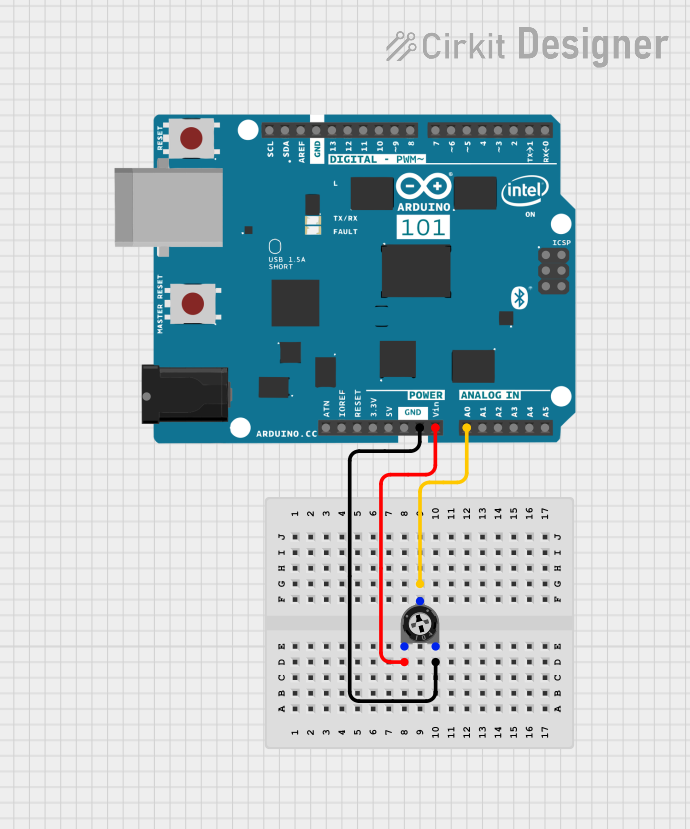 Open Project in Cirkit Designer
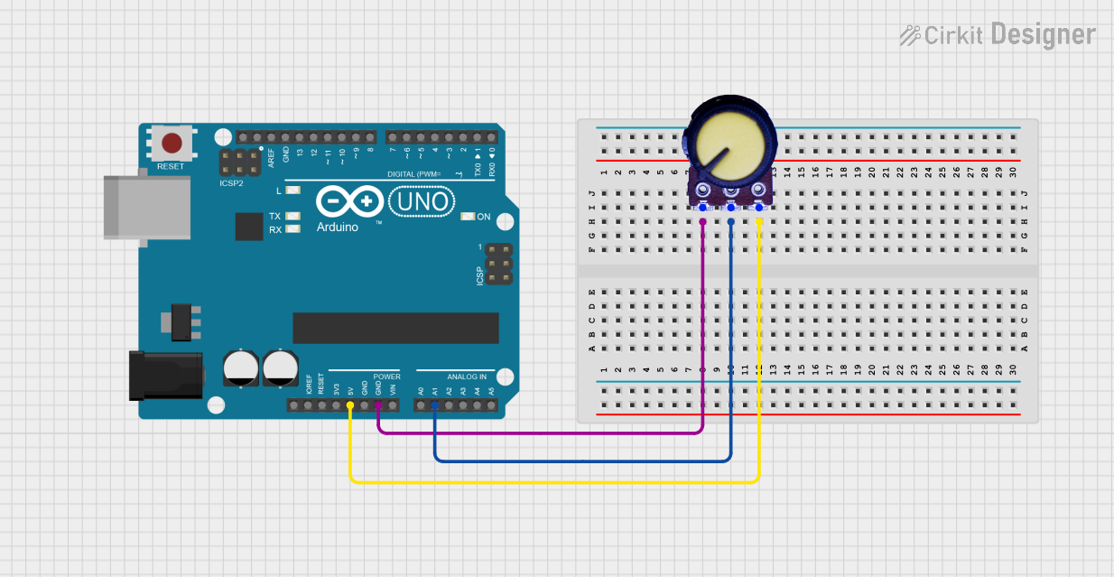 Open Project in Cirkit Designer
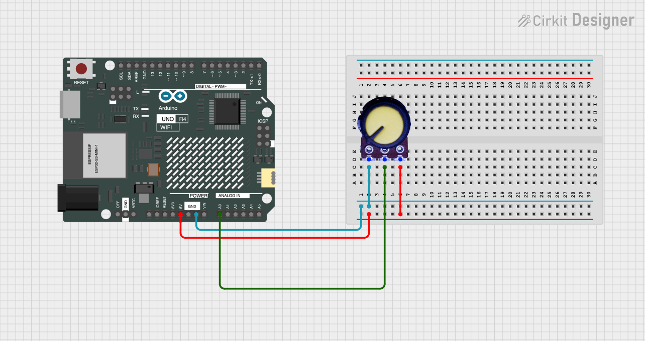 Open Project in Cirkit Designer
 Open Project in Cirkit Designer
Explore Projects Built with Potentiometer
Open Project in Cirkit DesignerOpen Project in Cirkit DesignerOpen Project in Cirkit DesignerOpen Project in Cirkit DesignerCommon Applications:
- Volume control in audio devices
- Brightness adjustment in LED circuits
- Signal tuning in analog circuits
- Position sensing in joysticks and rotary encoders
Technical Specifications
Below are the general technical specifications for a standard potentiometer. Note that specific values may vary depending on the model and manufacturer.
| Parameter | Specification |
|---|---|
| Resistance Range | 1 kΩ to 1 MΩ (common values: 10 kΩ, 100 kΩ) |
| Power Rating | 0.1 W to 2 W |
| Tolerance | ±10% to ±20% |
| Operating Voltage | Up to 50 V DC |
| Operating Temperature | -40°C to +125°C |
| Adjustment Type | Rotary or Linear (slider) |
Pin Configuration
A potentiometer typically has three pins:
| Pin | Description |
|---|---|
| Pin 1 | One end of the resistive track (fixed resistance point) |
| Pin 2 | Wiper (variable resistance point) |
| Pin 3 | Other end of the resistive track (fixed resistance point) |
Usage Instructions
How to Use a Potentiometer in a Circuit
Connect the Pins:
- Connect Pin 1 to the positive voltage supply (Vcc).
- Connect Pin 3 to ground (GND).
- Connect Pin 2 (the wiper) to the input of the circuit where you want to control the voltage.
Adjust the Resistance:
- Rotate the knob (for rotary potentiometers) or slide the lever (for linear potentiometers) to change the resistance between Pin 1 and Pin 2 or between Pin 2 and Pin 3.
- This adjustment changes the output voltage at Pin 2.
Voltage Divider Configuration:
- A potentiometer can act as a voltage divider. The output voltage at Pin 2 is determined by the ratio of resistances between Pin 1, Pin 2, and Pin 3.
Important Considerations:
- Power Rating: Ensure the potentiometer's power rating is not exceeded to avoid overheating or damage.
- Mechanical Durability: Avoid excessive force when turning the knob or sliding the lever to prevent mechanical wear.
- Noise: Some potentiometers may introduce electrical noise when adjusted. Use high-quality components for sensitive applications.
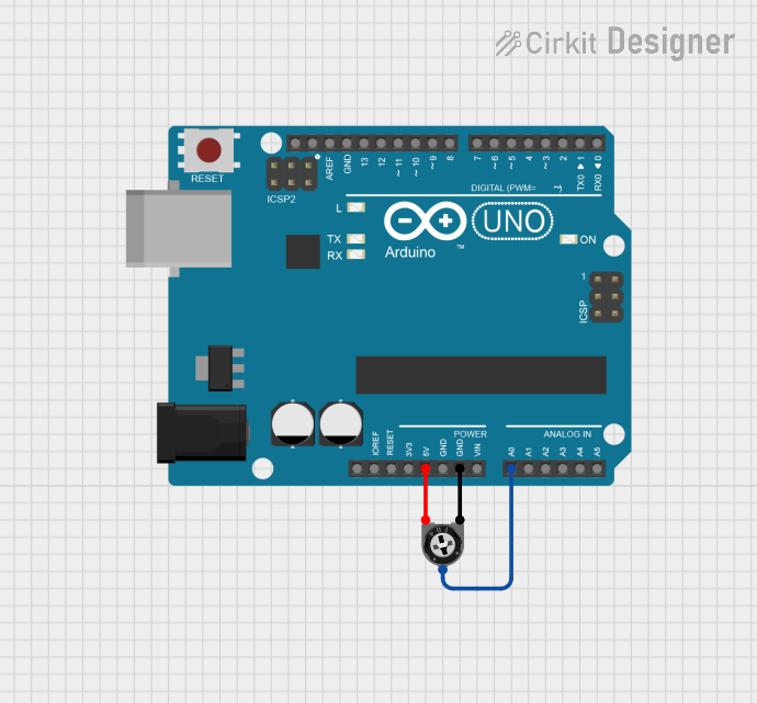
Example: Using a Potentiometer with Arduino UNO
Below is an example of how to use a potentiometer to control the brightness of an LED using an Arduino UNO.
// Example: Control LED brightness with a potentiometer and Arduino UNO

const int potPin = A0;  // Potentiometer connected to analog pin A0
const int ledPin = 9;   // LED connected to digital pin 9 (PWM pin)

void setup() {
  pinMode(ledPin, OUTPUT);  // Set LED pin as output
}

void loop() {
  int potValue = analogRead(potPin);  // Read potentiometer value (0-1023)

  // Map the potentiometer value to a PWM range (0-255)
  int ledBrightness = map(potValue, 0, 1023, 0, 255);

  analogWrite(ledPin, ledBrightness);  // Set LED brightness
}
Notes:
- Ensure the potentiometer is connected correctly to avoid incorrect readings.
- Use a current-limiting resistor with the LED to prevent damage.
Troubleshooting and FAQs
Common Issues:
No Output Voltage:
- Check the connections to ensure the potentiometer is wired correctly.
- Verify that the power supply is functioning and connected properly.
Inconsistent or Noisy Output:
- The potentiometer may be dirty or worn out. Clean the contacts or replace the component.
- Use a capacitor across the wiper and ground to reduce noise.
Overheating:
- Ensure the power rating of the potentiometer is not exceeded.
- Check for short circuits in the connected circuit.
FAQs:
Q: Can I use a potentiometer to control AC voltage?
A: Potentiometers are primarily designed for DC circuits. For AC applications, use a specialized variable transformer or dimmer circuit.
Q: How do I choose the right resistance value for my potentiometer?
A: Select a resistance value based on the desired voltage range and the input impedance of the connected circuit. Common values like 10 kΩ or 100 kΩ work for most applications.
Q: What is the difference between a linear and logarithmic potentiometer?
A: A linear potentiometer changes resistance uniformly, while a logarithmic potentiometer changes resistance exponentially, making it suitable for audio volume control.
By following this documentation, you can effectively use a potentiometer in your electronic projects!