How to Use SparkFun_I2S_Audio_Breakout: Examples, Pinouts, and Specs
Introduction
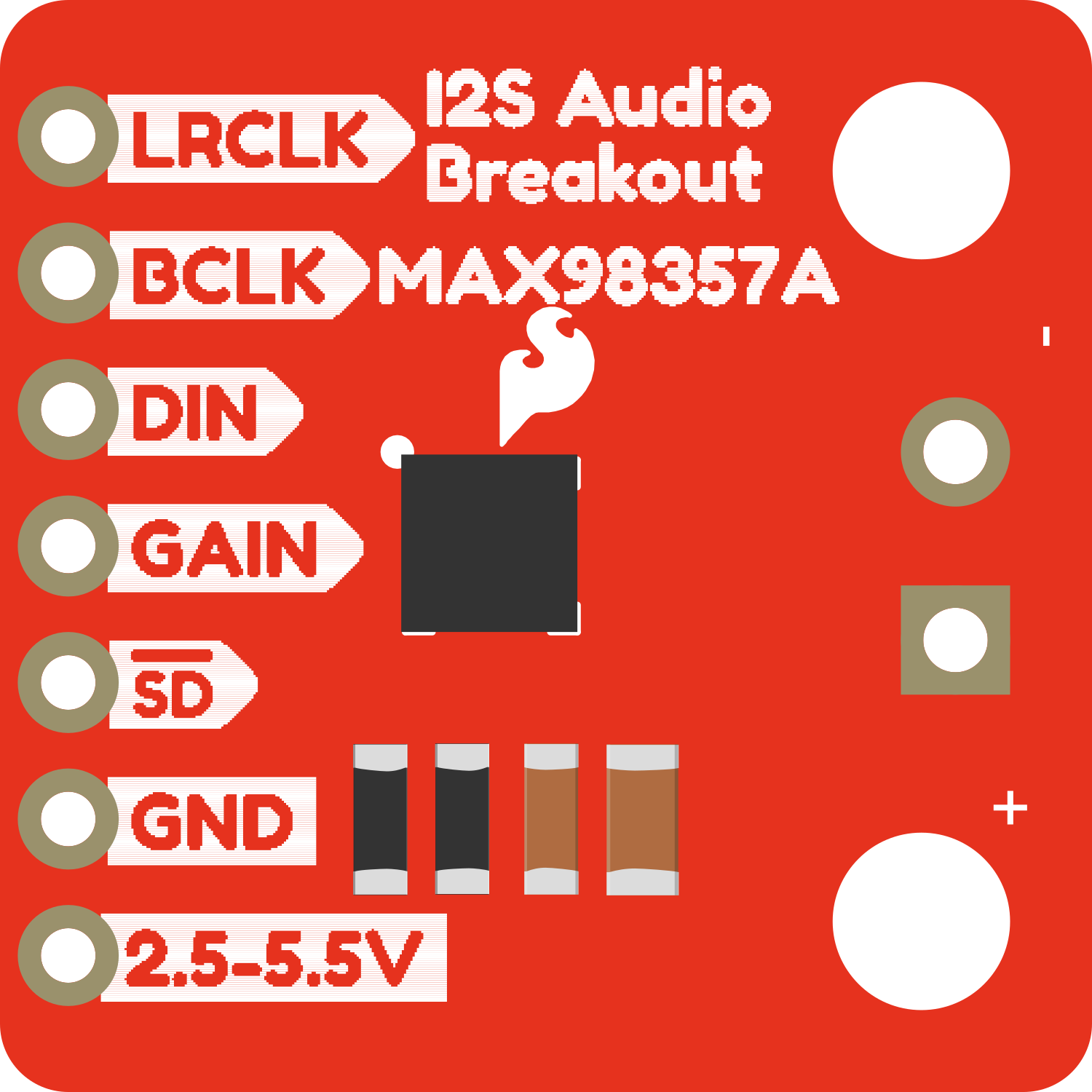
The SparkFun I2S Audio Breakout board is a versatile and easy-to-use component that facilitates the integration of digital audio into your projects. I2S, which stands for Inter-IC Sound, is a serial bus interface standard used for connecting digital audio devices. This breakout board is particularly useful for applications requiring high-quality audio input or output, such as voice recognition systems, audio sampling, and real-time audio processing.
Explore Projects Built with SparkFun_I2S_Audio_Breakout
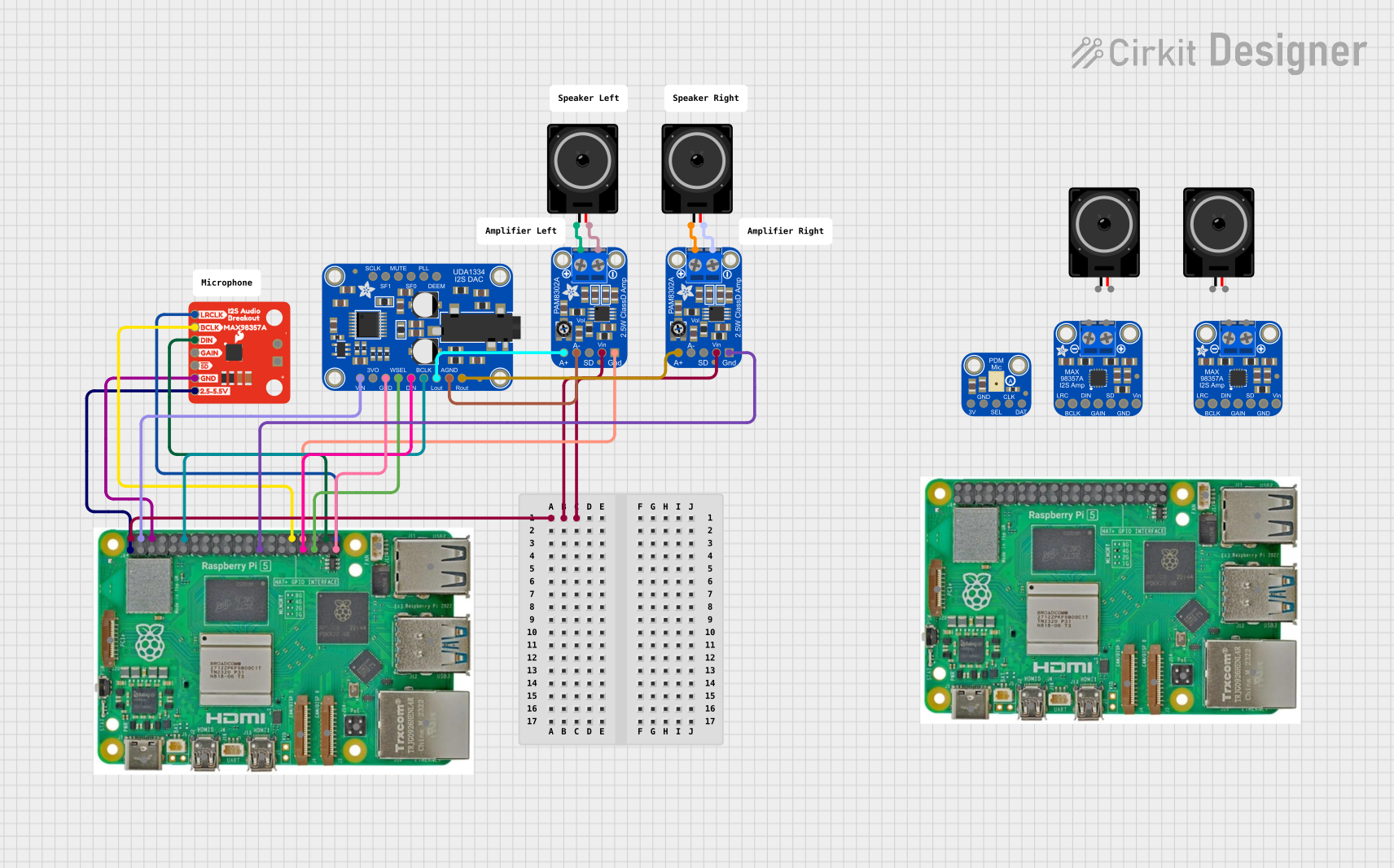
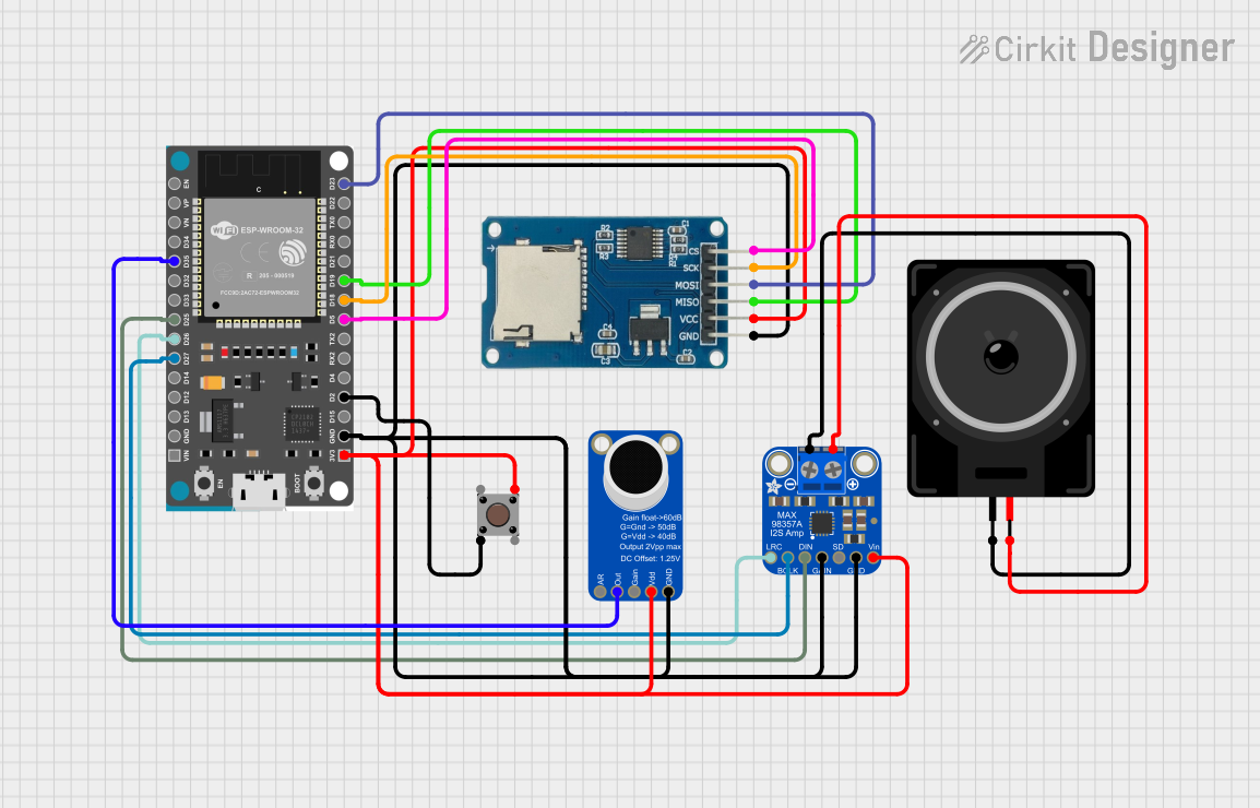
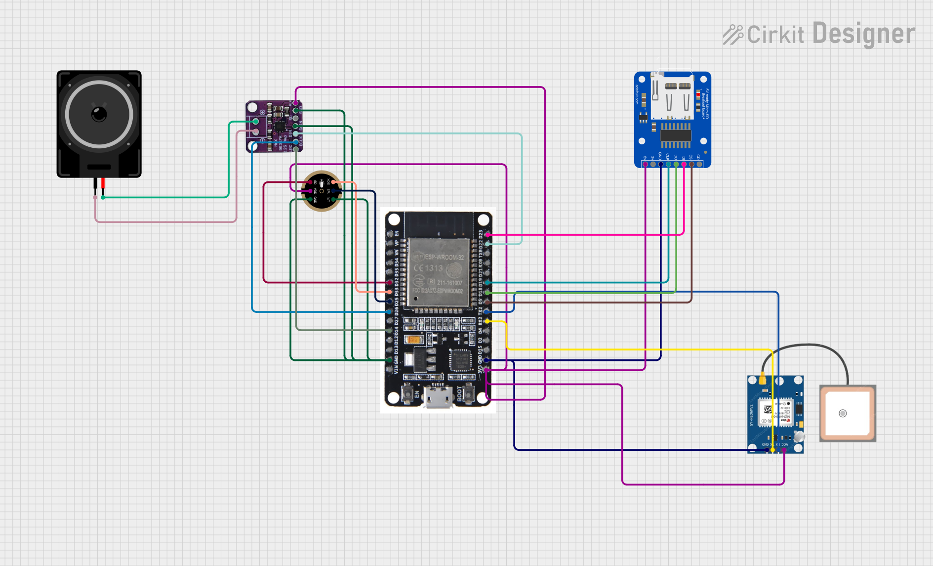
Explore Projects Built with SparkFun_I2S_Audio_Breakout
Common Applications and Use Cases
- Digital audio recorders
- Voice-activated devices
- Audio signal processing
- DIY synthesizers
- Sound effect generation
Technical Specifications
The SparkFun I2S Audio Breakout board is designed to be interfaced with microcontrollers and other devices capable of I2S communication. Below are the key technical specifications and pin configurations for the board.
Key Technical Details
- Supply Voltage: 3.3V to 5V
- Logic Levels: 3.3V (5V tolerant)
- Audio Format: I2S
- Sample Rates: Supports standard I2S sample rates
Pin Configuration and Descriptions
| Pin Number | Pin Name | Description |
|---|---|---|
| 1 | GND | Ground |
| 2 | VCC | Power supply (3.3V to 5V) |
| 3 | WS | Word Select/LRCLK (Left/Right Clock) |
| 4 | SD | Serial Data/AUDIODATA (Audio Data) |
| 5 | SCK | Serial Clock/BCLK (Bit Clock) |
| 6 | MCLK | Master Clock (optional for some devices) |
Usage Instructions
Interfacing with a Microcontroller
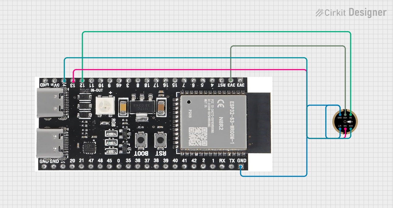
Power Connections: Connect the VCC pin to the power supply (3.3V or 5V, depending on your microcontroller), and the GND pin to the ground.
I2S Connections: Connect the WS, SD, and SCK pins to the corresponding I2S pins on your microcontroller. If your microcontroller or audio device requires a Master Clock (MCLK), connect it as well.
Programming: Write or upload an I2S-compatible code to your microcontroller to handle audio data transmission.
Important Considerations and Best Practices
- Ensure that the power supply voltage matches the requirements of both the SparkFun I2S Audio Breakout and the microcontroller.
- Use pull-up or pull-down resistors on the I2S lines if recommended by your microcontroller's datasheet.
- Keep the I2S signal lines as short as possible to minimize electromagnetic interference.
- If using multiple digital audio devices, ensure that they are properly synchronized.
Troubleshooting and FAQs
Common Issues
- No Audio Output: Check the connections and ensure that the microcontroller is correctly programmed for I2S communication.
- Distorted Audio: Verify that the sample rate and bit depth match between the audio source and the microcontroller.
Solutions and Tips for Troubleshooting
- Double-check wiring, especially the I2S signal lines.
- Use an oscilloscope to verify that the I2S signals are being transmitted correctly.
- Ensure that the power supply is stable and within the specified voltage range.
FAQs
Q: Can I use this board with a 5V microcontroller? A: Yes, the board is 5V tolerant, but ensure that the logic levels are compatible.
Q: Do I need an external MCLK? A: It depends on your microcontroller and audio device. Some devices require an MCLK, while others can generate it internally.
Q: What audio sample rates does the board support? A: The board supports standard I2S sample rates. Check your microcontroller's capabilities for specific rates.
Example Code for Arduino UNO
Below is a simple example code snippet for initializing I2S communication with the SparkFun I2S Audio Breakout using an Arduino UNO. This example assumes you have the appropriate I2S library installed.
#include <I2S.h>

// Define the I2S pins for the Arduino UNO
const int i2s_ws_pin = 10;   // LRCLK
const int i2s_sd_pin = 11;   // AUDIODATA
const int i2s_sck_pin = 13;  // BCLK

void setup() {
  // Initialize I2S with the standard sample rate and bit depth
  if (!I2S.begin(I2S_PHILIPS_MODE, 44100, 16)) {
    Serial.println("Failed to initialize I2S!");
    while (1); // Halt if I2S initialization fails
  }
}

void loop() {
  // Your audio processing code goes here
}
Remember to adjust the pin definitions according to your specific setup and ensure that the I2S library supports your microcontroller.