Cirkit Designer
Your all-in-one circuit design IDE
Home /
Component Documentation
How to Use PZEM-04T: Examples, Pinouts, and Specs
Introduction
The PZEM-04T is a multifunctional electrical parameter measurement module designed to measure voltage, current, power, and energy. This versatile module is widely used in energy monitoring and management systems, providing accurate and real-time data for various applications. Whether you are working on a home automation project, industrial energy management, or renewable energy systems, the PZEM-04T offers a reliable solution for monitoring electrical parameters.
Explore Projects Built with PZEM-04T
ESP32-Based Smart Environmental Monitoring System with Relay Control

This is a smart environmental monitoring and control system featuring an ESP32 microcontroller interfaced with a PZEM004T for power monitoring, relay modules for actuating bulbs and a fan, and an LCD for user interface. It includes flame, gas, and vibration sensors for safety monitoring purposes.
ESP32-Controlled AC Lighting System with Power Monitoring

This circuit features an ESP32 microcontroller interfaced with a PZEM004T power monitoring module and a 4-channel relay module controlling multiple AC LED bulbs. The ESP32 uses GPIO pins to control the relays, which in turn switch the LED bulbs on and off. The PZEM004T is connected to the ESP32 for communication and to a current sensor for monitoring power consumption of the connected load through the relay contacts.
ESP32-Based Smart Energy Monitoring and Control System with PZEM004t and LCD Display
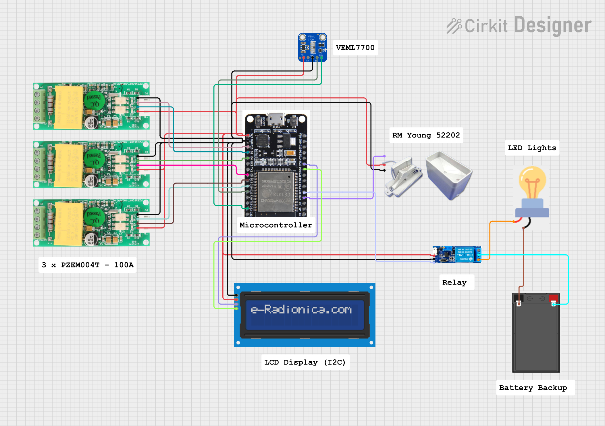
This circuit is a monitoring and control system using an ESP32 microcontroller. It integrates multiple PZEM004t energy meters, a rain gauge, a light sensor, and an LCD display for data visualization. Additionally, it controls a relay module to switch a bulb on or off based on sensor inputs.
ESP32 and PZEM004T-Based Smart Light Control with Current Sensing
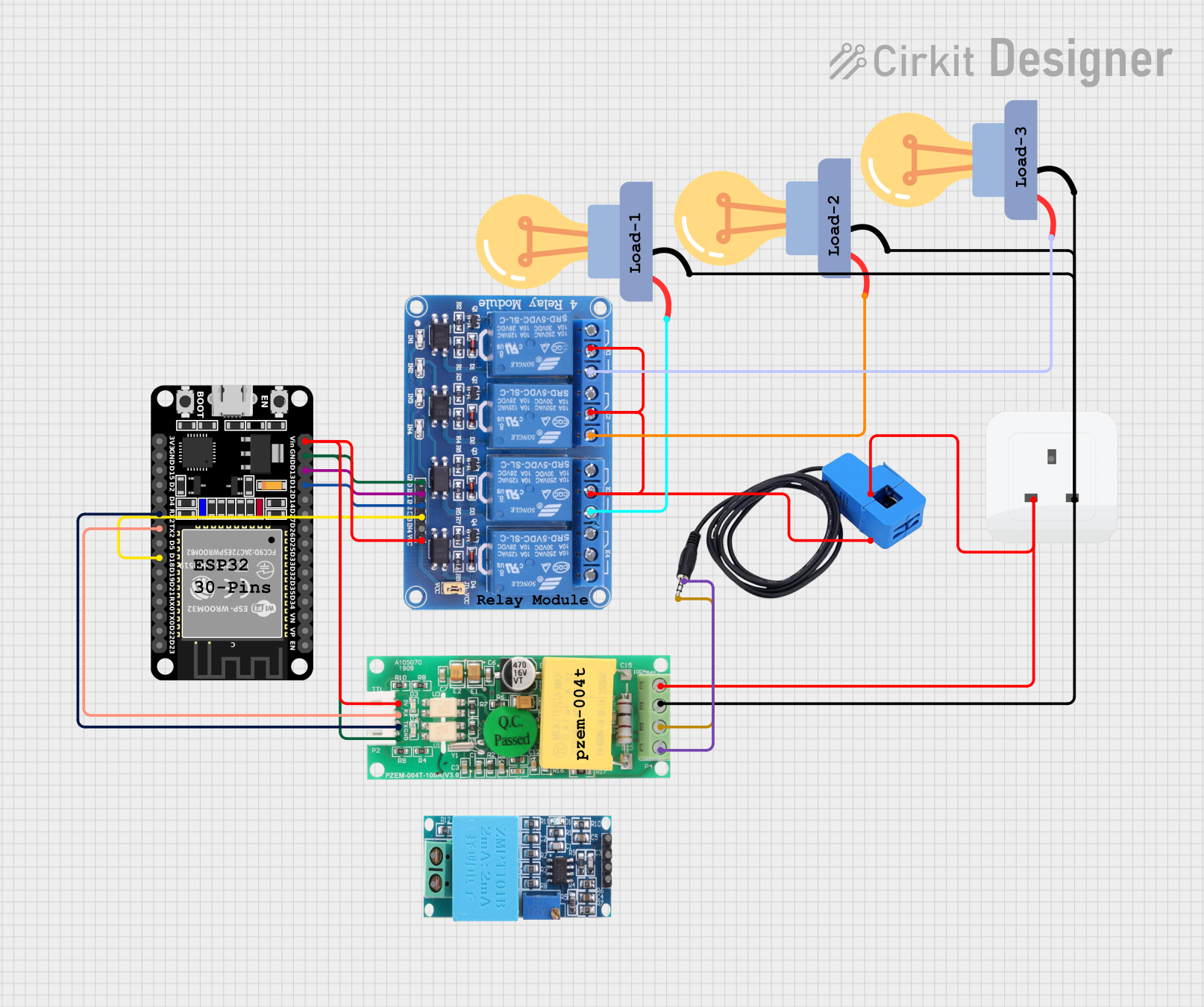
This circuit is designed for monitoring and controlling AC loads using an ESP32 microcontroller. It includes a PZEM004T module for measuring voltage, current, and power, and a 4-channel relay module to switch three LED bulbs. The ESP32 communicates with the PZEM004T via UART and controls the relays to manage the connected loads.
Explore Projects Built with PZEM-04T
ESP32-Based Smart Environmental Monitoring System with Relay Control
This is a smart environmental monitoring and control system featuring an ESP32 microcontroller interfaced with a PZEM004T for power monitoring, relay modules for actuating bulbs and a fan, and an LCD for user interface. It includes flame, gas, and vibration sensors for safety monitoring purposes.
ESP32-Controlled AC Lighting System with Power Monitoring
This circuit features an ESP32 microcontroller interfaced with a PZEM004T power monitoring module and a 4-channel relay module controlling multiple AC LED bulbs. The ESP32 uses GPIO pins to control the relays, which in turn switch the LED bulbs on and off. The PZEM004T is connected to the ESP32 for communication and to a current sensor for monitoring power consumption of the connected load through the relay contacts.
ESP32-Based Smart Energy Monitoring and Control System with PZEM004t and LCD Display
This circuit is a monitoring and control system using an ESP32 microcontroller. It integrates multiple PZEM004t energy meters, a rain gauge, a light sensor, and an LCD display for data visualization. Additionally, it controls a relay module to switch a bulb on or off based on sensor inputs.
ESP32 and PZEM004T-Based Smart Light Control with Current Sensing
This circuit is designed for monitoring and controlling AC loads using an ESP32 microcontroller. It includes a PZEM004T module for measuring voltage, current, and power, and a 4-channel relay module to switch three LED bulbs. The ESP32 communicates with the PZEM004T via UART and controls the relays to manage the connected loads.
Technical Specifications
Key Technical Details
| Parameter | Value |
|---|---|
| Voltage Range | 80-260V AC |
| Current Range | 0-100A (with external CT) |
| Power Range | 0-22kW |
| Energy Range | 0-9999kWh |
| Frequency | 45-65Hz |
| Communication | TTL (3.3V) |
| Accuracy | ±1% |
| Power Supply | 5V DC |
Pin Configuration and Descriptions
| Pin Number | Pin Name | Description |
|---|---|---|
| 1 | VCC | Power supply (5V DC) |
| 2 | GND | Ground |
| 3 | RX | UART Receive (TTL 3.3V) |
| 4 | TX | UART Transmit (TTL 3.3V) |
| 5 | A | AC Voltage Input (Live) |
| 6 | B | AC Voltage Input (Neutral) |
| 7 | CT | Current Transformer Input |
Usage Instructions
How to Use the PZEM-04T in a Circuit
- Power Supply: Connect the VCC pin to a 5V DC power supply and the GND pin to the ground.
- Voltage Measurement: Connect the A and B pins to the live and neutral wires of the AC voltage you want to measure.
- Current Measurement: Connect the external current transformer (CT) to the CT pin. Ensure the CT is properly clamped around the live wire of the AC circuit.
- Communication: Connect the RX and TX pins to the corresponding UART pins of your microcontroller (e.g., Arduino UNO).
Important Considerations and Best Practices
- Safety First: Always ensure the module is powered off before making any connections to avoid electric shock.
- Proper Clamping: Ensure the current transformer is securely clamped around the live wire for accurate current measurement.
- Stable Power Supply: Use a stable 5V DC power supply to avoid fluctuations in readings.
- Isolation: If necessary, use optocouplers or isolation circuits to protect your microcontroller from high voltage.
Sample Arduino Code
#include <SoftwareSerial.h>

// Define the RX and TX pins for SoftwareSerial
SoftwareSerial pzem(10, 11); // RX, TX

void setup() {
  Serial.begin(9600); // Initialize serial communication at 9600 baud
  pzem.begin(9600);   // Initialize PZEM communication at 9600 baud
}

void loop() {
  // Request data from PZEM-04T
  pzem.write(0xB0); // Command to read voltage
  delay(100);       // Wait for the response

  if (pzem.available()) {
    // Read the response
    byte response[7];
    for (int i = 0; i < 7; i++) {
      response[i] = pzem.read();
    }

    // Extract voltage value from the response
    float voltage = (response[2] << 8 | response[3]) / 10.0;

    // Print the voltage value to the serial monitor
    Serial.print("Voltage: ");
    Serial.print(voltage);
    Serial.println(" V");
  }

  delay(1000); // Wait for 1 second before the next reading
}
Troubleshooting and FAQs
Common Issues Users Might Face
- No Data Received: Ensure the RX and TX pins are correctly connected and the baud rate matches.
- Inaccurate Readings: Verify the current transformer is properly clamped and the module is powered by a stable 5V DC supply.
- Module Not Responding: Check all connections and ensure the module is not damaged.
Solutions and Tips for Troubleshooting
- Check Connections: Double-check all wiring and connections to ensure they are secure and correct.
- Use a Stable Power Supply: Ensure the power supply is stable and within the specified range.
- Verify Baud Rate: Ensure the baud rate for communication matches the module's default (9600 baud).
- Inspect the CT: Make sure the current transformer is properly clamped around the live wire and not damaged.
By following this documentation, you should be able to effectively integrate and use the PZEM-04T module in your projects, ensuring accurate and reliable electrical parameter measurements.