How to Use R4 Minuma: Examples, Pinouts, and Specs
Introduction
The R4 Minuma is a precision resistor designed for applications requiring highly accurate and stable resistance values. Known for its reliability and low tolerance, the R4 Minuma is widely used in circuits where precise current control, voltage division, or signal conditioning is critical. Its robust design ensures minimal drift over time and temperature variations, making it ideal for both industrial and consumer electronics.
Explore Projects Built with R4 Minuma

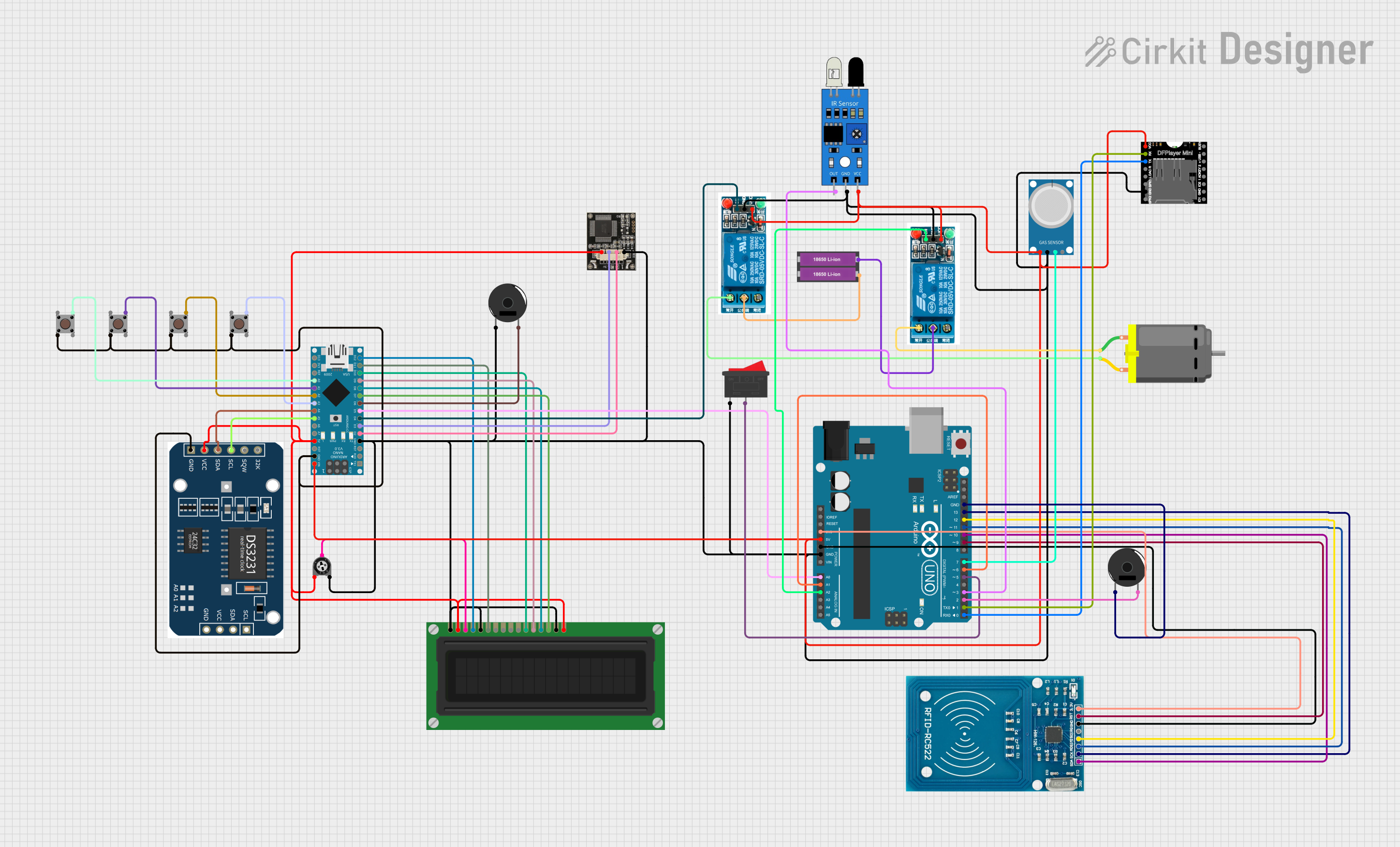
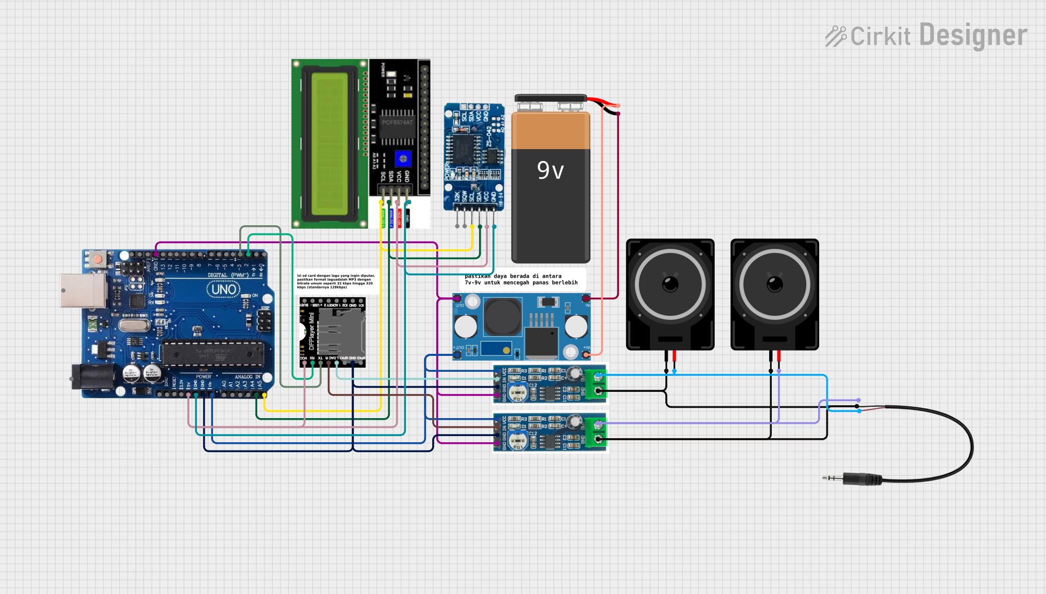
Explore Projects Built with R4 Minuma
Common Applications
- Precision measurement equipment
- Voltage dividers in analog circuits
- Signal conditioning in sensor interfaces
- Calibration circuits
- High-accuracy current limiting in power supplies
Technical Specifications
The R4 Minuma resistor is available in various resistance values and power ratings. Below are the general specifications:
| Parameter | Value |
|---|---|
| Resistance Range | 10 Ω to 1 MΩ |
| Tolerance | ±0.1% |
| Power Rating | 0.25 W, 0.5 W, 1 W |
| Temperature Coefficient | ±15 ppm/°C |
| Operating Temperature | -55°C to +125°C |
| Maximum Voltage | 200 V |
| Package Type | Axial or Surface Mount (SMD) |
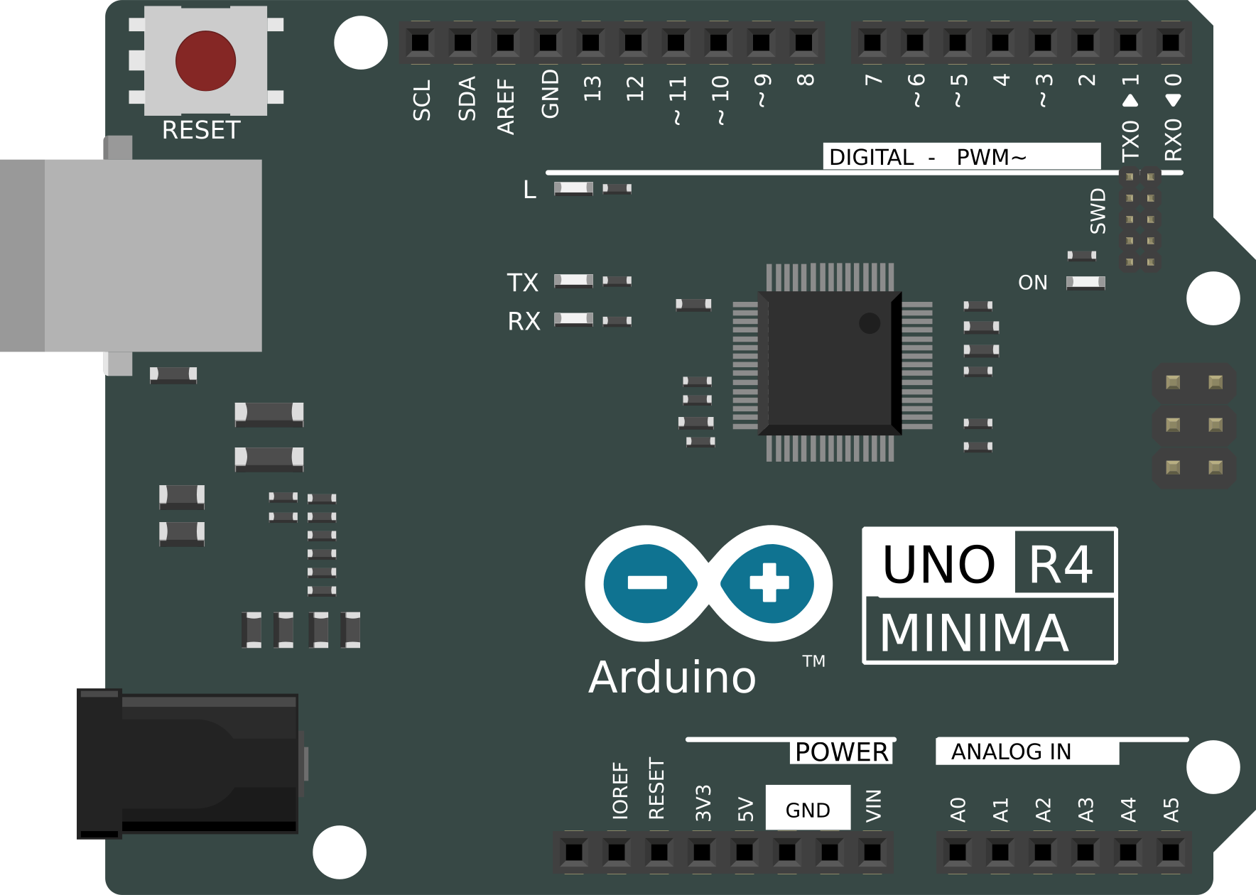
Pin Configuration and Descriptions
The R4 Minuma is a two-terminal passive component. Below is the pin configuration:
| Pin | Description |
|---|---|
| Lead 1 | Connects to one side of the circuit |
| Lead 2 | Connects to the other side of the circuit |
For surface-mount versions, the terminals are labeled as Terminal 1 and Terminal 2, with no polarity.
Usage Instructions
How to Use the R4 Minuma in a Circuit
- Determine the Required Resistance Value: Select the appropriate R4 Minuma resistor based on the desired resistance value and power rating for your circuit.
- Placement in the Circuit:
- For through-hole versions, insert the leads into the PCB holes and solder them securely.
- For SMD versions, align the resistor on the PCB pads and solder it using reflow or manual soldering techniques.
- Verify Connections: Ensure that the resistor is connected in the correct position within the circuit, as per the schematic.
- Power Considerations: Ensure the resistor's power rating is not exceeded during operation to prevent overheating or damage.
Important Considerations and Best Practices
- Power Dissipation: Always choose a resistor with a power rating higher than the expected power dissipation in the circuit.
- Temperature Stability: For applications with significant temperature variations, consider the resistor's temperature coefficient to ensure stability.
- Parasitic Effects: In high-frequency circuits, account for the resistor's parasitic inductance and capacitance.
- Testing: Use a multimeter to verify the resistance value before installation.
Example: Using R4 Minuma with an Arduino UNO
The R4 Minuma can be used in conjunction with an Arduino UNO for applications such as voltage dividers or current limiting. Below is an example of using the R4 Minuma in a voltage divider circuit to measure an analog voltage:
Circuit Diagram
- Connect one terminal of the R4 Minuma (e.g., 10 kΩ) to the voltage source.
- Connect the other terminal to the analog input pin (A0) of the Arduino UNO.
- Add a second resistor (e.g., 10 kΩ) between the analog input pin and ground.
Arduino Code
// Example code to read voltage using a voltage divider with R4 Minuma
const int analogPin = A0; // Analog pin connected to the voltage divider
float referenceVoltage = 5.0; // Reference voltage of the Arduino UNO
float resistor1 = 10000.0; // Resistance of R4 Minuma (in ohms)
float resistor2 = 10000.0; // Resistance of the second resistor (in ohms)

void setup() {
  Serial.begin(9600); // Initialize serial communication
}

void loop() {
  int analogValue = analogRead(analogPin); // Read the analog input
  float voltage = (analogValue / 1023.0) * referenceVoltage; // Calculate voltage
  float inputVoltage = voltage * ((resistor1 + resistor2) / resistor2);
  // Calculate the input voltage using the voltage divider formula

  Serial.print("Input Voltage: ");
  Serial.print(inputVoltage);
  Serial.println(" V");

  delay(1000); // Wait for 1 second before the next reading
}
Troubleshooting and FAQs
Common Issues
Incorrect Resistance Value:
- Cause: Misreading the resistor's color code or selecting the wrong part.
- Solution: Double-check the resistance value using a multimeter before installation.
Overheating:
- Cause: Exceeding the resistor's power rating.
- Solution: Use a resistor with a higher power rating or reduce the current in the circuit.
Unstable Readings in Precision Circuits:
- Cause: High temperature coefficient or poor soldering connections.
- Solution: Ensure proper soldering and use resistors with a low temperature coefficient.
Parasitic Effects in High-Frequency Circuits:
- Cause: Parasitic inductance or capacitance of the resistor.
- Solution: Use specialized low-inductance resistors for high-frequency applications.
FAQs
Q1: Can the R4 Minuma be used in high-power circuits?
A1: The R4 Minuma is available in power ratings up to 1 W. For higher power applications, consider using multiple resistors in parallel or series to distribute the power dissipation.
Q2: How do I identify the resistance value of the R4 Minuma?
A2: For through-hole versions, use the color code on the resistor body. For SMD versions, refer to the printed code on the component.
Q3: What is the maximum voltage the R4 Minuma can handle?
A3: The maximum voltage rating is 200 V. Ensure the applied voltage does not exceed this limit to avoid damage.
Q4: Can I use the R4 Minuma in AC circuits?
A4: Yes, the R4 Minuma can be used in both AC and DC circuits, provided the voltage and power ratings are not exceeded.