Cirkit Designer
Your all-in-one circuit design IDE
Home /
Component Documentation
How to Use MOTOR DRIVER: Examples, Pinouts, and Specs
Introduction
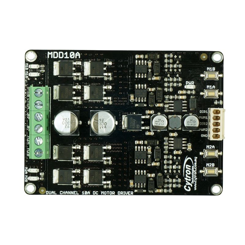
The CRYTON MD10A Motor Driver is an electronic device designed to provide the necessary current and voltage to drive a motor. It includes features for controlling the speed, direction, and torque of the motor, making it an essential component in various applications. Common use cases include robotics, automation systems, electric vehicles, and any project requiring precise motor control.
Explore Projects Built with MOTOR DRIVER
L298N DC Motor Driver Controlled DC Motor System
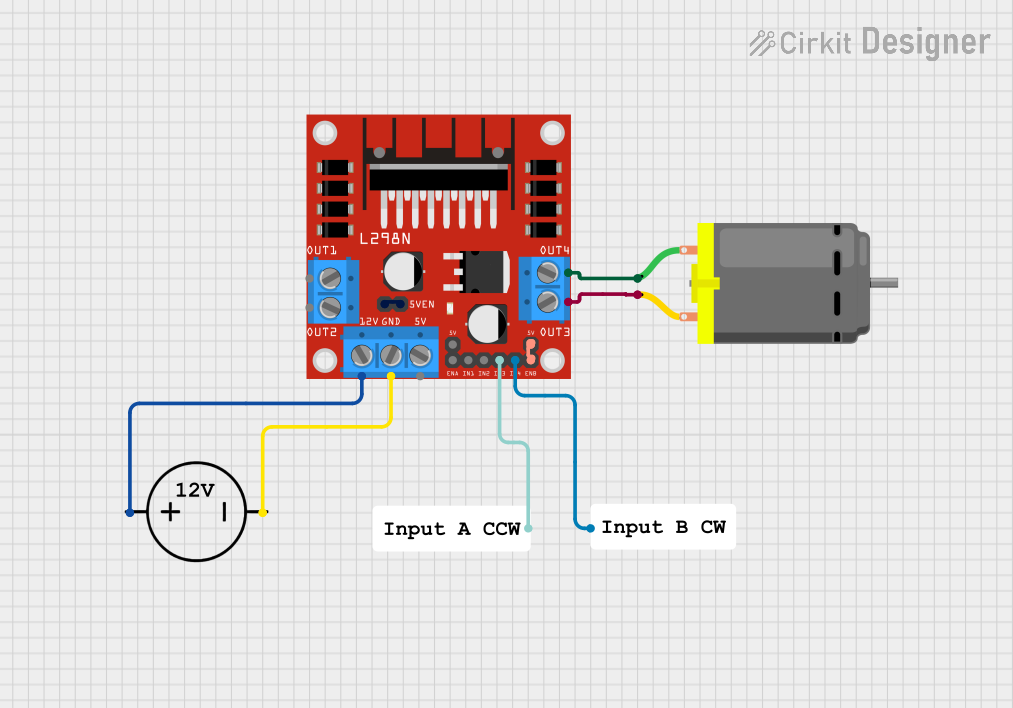
This circuit is designed to control a DC motor using an L298N motor driver module. The motor driver is powered by a DC power source and interfaces with the motor through its output pins, while resistors are used to manage the input signals to the driver.
DC Motor Control System with BTS7960 Motor Driver and Arcade Buttons

This circuit controls a DC motor using a BTS7960 motor driver, powered by a 12V power supply and regulated by a DC-DC step-down converter. The motor's operation is controlled via two arcade buttons and a rocker switch, allowing for user input to manage the motor's direction and power.
ESP32 and L298N Motor Driver Controlled Battery-Powered Robotic Car

This circuit is a motor control system powered by a 12V battery, utilizing an L298N motor driver to control four DC gearmotors. An ESP32 microcontroller is used to send control signals to the motor driver, enabling precise control of the motors for applications such as a robotic vehicle.
ESP32-Controlled Dual Motor Driver with Optical Encoder Feedback

This circuit is designed to control two DC motors using an L298N Dual Motor Driver Module, which receives PWM control signals from an ESP32 microcontroller. The motors' rotational movement can be monitored by two Optical Encoder Sensor Modules connected to the ESP32. Power is supplied by a 4 x AAA battery mount, with the battery's positive terminal connected to the motor driver's 12V input and the negative terminal to the common ground.
Explore Projects Built with MOTOR DRIVER
L298N DC Motor Driver Controlled DC Motor System
This circuit is designed to control a DC motor using an L298N motor driver module. The motor driver is powered by a DC power source and interfaces with the motor through its output pins, while resistors are used to manage the input signals to the driver.
DC Motor Control System with BTS7960 Motor Driver and Arcade Buttons
This circuit controls a DC motor using a BTS7960 motor driver, powered by a 12V power supply and regulated by a DC-DC step-down converter. The motor's operation is controlled via two arcade buttons and a rocker switch, allowing for user input to manage the motor's direction and power.
ESP32 and L298N Motor Driver Controlled Battery-Powered Robotic Car
This circuit is a motor control system powered by a 12V battery, utilizing an L298N motor driver to control four DC gearmotors. An ESP32 microcontroller is used to send control signals to the motor driver, enabling precise control of the motors for applications such as a robotic vehicle.
ESP32-Controlled Dual Motor Driver with Optical Encoder Feedback
This circuit is designed to control two DC motors using an L298N Dual Motor Driver Module, which receives PWM control signals from an ESP32 microcontroller. The motors' rotational movement can be monitored by two Optical Encoder Sensor Modules connected to the ESP32. Power is supplied by a 4 x AAA battery mount, with the battery's positive terminal connected to the motor driver's 12V input and the negative terminal to the common ground.
Technical Specifications
Key Technical Details
| Parameter | Value |
|---|---|
| Operating Voltage | 5V to 30V |
| Continuous Current | 10A |
| Peak Current | 15A |
| Control Logic | TTL/CMOS compatible |
| PWM Frequency | Up to 20 kHz |
| Operating Temperature | -40°C to 85°C |
| Dimensions | 60mm x 45mm x 20mm |
Pin Configuration and Descriptions
| Pin Number | Pin Name | Description |
|---|---|---|
| 1 | VCC | Power supply input (5V to 30V) |
| 2 | GND | Ground |
| 3 | IN1 | Control input 1 (Direction control) |
| 4 | IN2 | Control input 2 (Direction control) |
| 5 | PWM | Pulse Width Modulation input (Speed control) |
| 6 | OUT1 | Motor output 1 |
| 7 | OUT2 | Motor output 2 |
| 8 | EN | Enable pin (Active high to enable the driver) |
Usage Instructions
How to Use the Component in a Circuit
Power Supply Connection:
- Connect the VCC pin to a power supply ranging from 5V to 30V.
- Connect the GND pin to the ground of the power supply.
Motor Connection:
- Connect the motor terminals to the OUT1 and OUT2 pins.
Control Inputs:
- Connect IN1 and IN2 to digital output pins of a microcontroller (e.g., Arduino UNO) to control the direction of the motor.
- Connect the PWM pin to a PWM-capable output pin of the microcontroller to control the speed of the motor.
- Connect the EN pin to a digital output pin of the microcontroller to enable or disable the motor driver.
Important Considerations and Best Practices
- Ensure that the power supply voltage does not exceed the specified range (5V to 30V).
- Use appropriate heat sinks or cooling mechanisms if the motor driver is operating at high currents for extended periods.
- Implement proper decoupling capacitors close to the VCC and GND pins to minimize noise and voltage spikes.
- Verify the connections and polarity before powering up the circuit to avoid damage to the motor driver and other components.
Example Code for Arduino UNO
// Define the motor driver pins
const int IN1 = 2;
const int IN2 = 3;
const int PWM = 5;
const int EN = 4;

void setup() {
  // Set the motor driver pins as outputs
  pinMode(IN1, OUTPUT);
  pinMode(IN2, OUTPUT);
  pinMode(PWM, OUTPUT);
  pinMode(EN, OUTPUT);

  // Enable the motor driver
  digitalWrite(EN, HIGH);
}

void loop() {
  // Rotate the motor in one direction
  digitalWrite(IN1, HIGH);
  digitalWrite(IN2, LOW);
  analogWrite(PWM, 128); // Set speed (0-255)

  delay(2000); // Run for 2 seconds

  // Stop the motor
  analogWrite(PWM, 0);
  delay(1000); // Wait for 1 second

  // Rotate the motor in the opposite direction
  digitalWrite(IN1, LOW);
  digitalWrite(IN2, HIGH);
  analogWrite(PWM, 128); // Set speed (0-255)

  delay(2000); // Run for 2 seconds

  // Stop the motor
  analogWrite(PWM, 0);
  delay(1000); // Wait for 1 second
}
Troubleshooting and FAQs
Common Issues Users Might Face
Motor Not Running:
- Solution: Check the power supply connections and ensure the EN pin is set to HIGH. Verify the control inputs (IN1, IN2, and PWM) are correctly connected and configured.
Motor Running in the Wrong Direction:
- Solution: Swap the connections of IN1 and IN2 or adjust the control logic in the code.
Motor Speed Not Changing:
- Solution: Ensure the PWM pin is connected to a PWM-capable output pin on the microcontroller. Verify the PWM signal is being generated correctly.
Overheating:
- Solution: Use appropriate heat sinks or cooling mechanisms. Ensure the motor driver is not operating beyond its current rating.
Solutions and Tips for Troubleshooting
- Check Connections: Ensure all connections are secure and correctly oriented.
- Use a Multimeter: Measure the voltage at various points in the circuit to verify proper operation.
- Consult the Datasheet: Refer to the CRYTON MD10A datasheet for detailed information and additional troubleshooting tips.
- Test with a Known Good Motor: If possible, test the motor driver with a known good motor to isolate the issue.
By following this documentation, users can effectively utilize the CRYTON MD10A Motor Driver in their projects, ensuring reliable and efficient motor control.