How to Use Touch sensor TP233: Examples, Pinouts, and Specs
Introduction
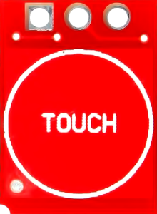
The Touch Sensor TP233 (manufacturer part ID: TTP233H-HA6) is a capacitive touch sensor IC designed by Tontek Design Technology. It detects touch input and converts it into an electrical signal, enabling touch-based user interfaces for electronic devices. This sensor is highly sensitive, compact, and easy to integrate into various applications.
Explore Projects Built with Touch sensor TP233
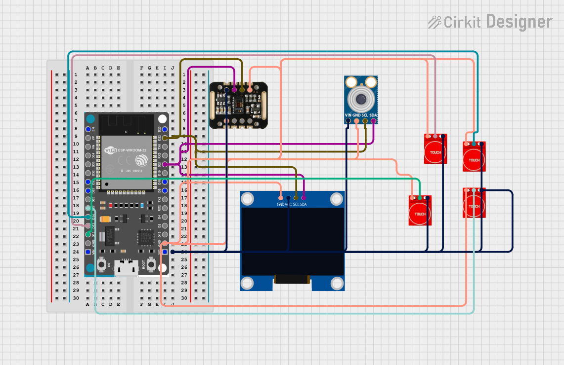

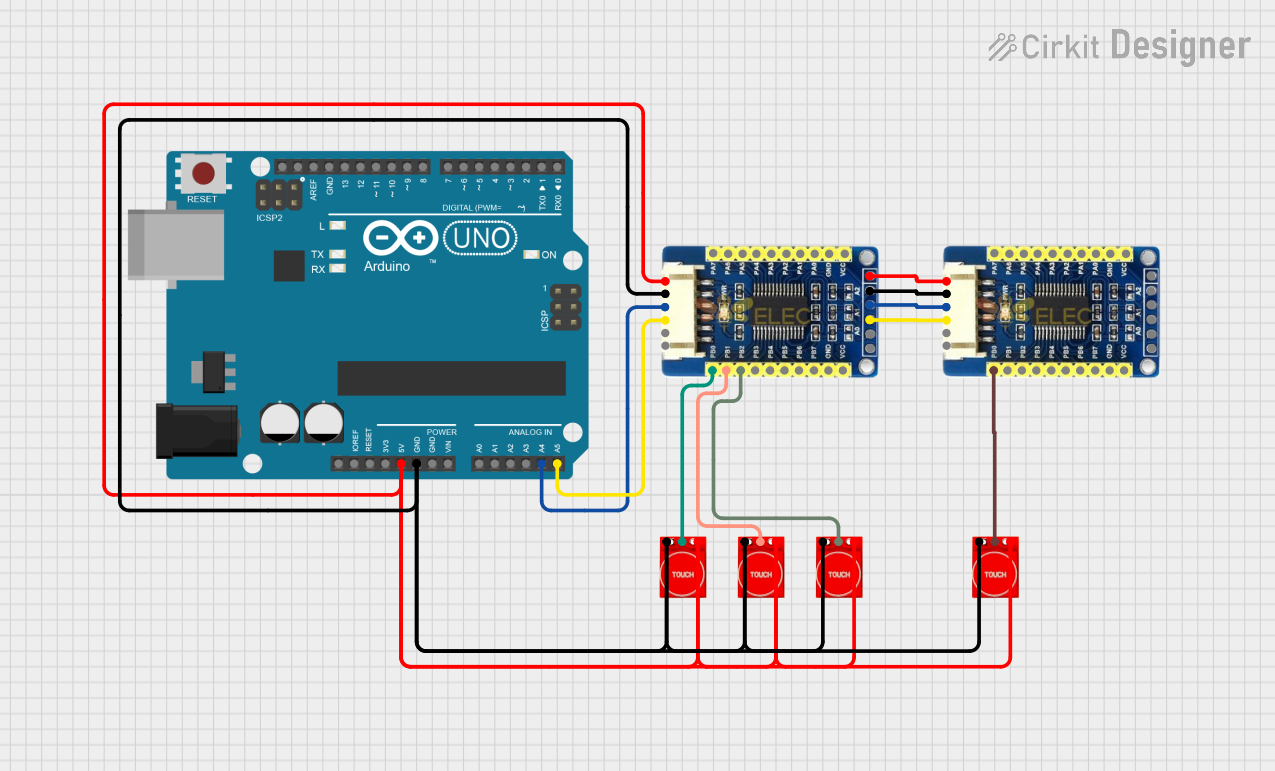
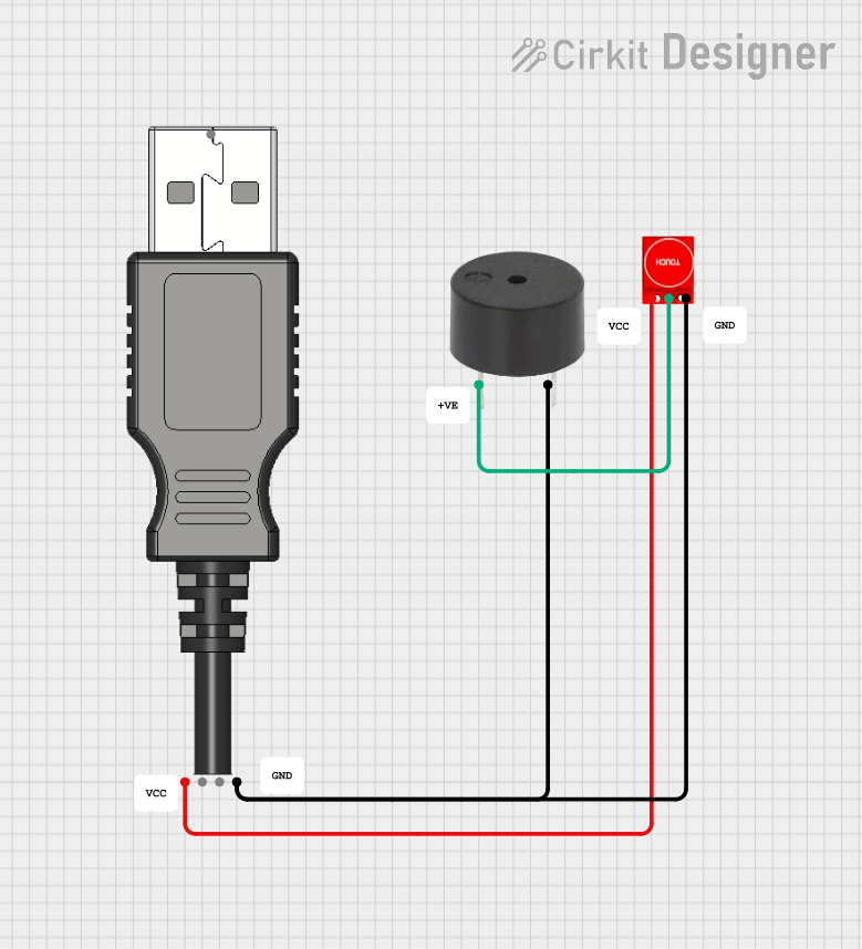
Explore Projects Built with Touch sensor TP233
Common Applications and Use Cases
- Touch-sensitive buttons for home appliances
- Capacitive touch panels for consumer electronics
- Replacement for mechanical buttons in embedded systems
- Interactive kiosks and control panels
- Wearable devices and IoT applications
Technical Specifications
The TP233 touch sensor is designed for low-power operation and high sensitivity. Below are its key technical details:
| Parameter | Value |
|---|---|
| Operating Voltage | 2.0V to 5.5V |
| Operating Current | < 8µA (at 3V, no load) |
| Response Time | ~60ms (at fast mode) |
| Output Type | Active Low (default) |
| Touch Sensitivity | Adjustable via external capacitor |
| Operating Temperature | -40°C to +85°C |
| Package Type | SOT-23-6 |
Pin Configuration and Descriptions
The TP233 is available in a 6-pin SOT-23-6 package. Below is the pinout and description:
| Pin Number | Pin Name | Description |
|---|---|---|
| 1 | VDD | Power supply input (2.0V to 5.5V). Connect to the positive terminal of the power source. |
| 2 | OUT | Output pin. Outputs a low signal when touch is detected. |
| 3 | AHLB | Active High/Low configuration. Connect to GND for active low output (default). |
| 4 | MODE | Mode selection pin. Connect to GND for fast mode or VDD for low-power mode. |
| 5 | VSS | Ground pin. Connect to the negative terminal of the power source. |
| 6 | TTP | Touch input pin. Connect to the touch pad or electrode. |
Usage Instructions
How to Use the TP233 in a Circuit
- Power Supply: Connect the VDD pin to a 2.0V–5.5V power source and the VSS pin to ground.
- Touch Pad Connection: Attach a conductive touch pad (e.g., copper or ITO) to the TTP pin. Ensure the pad is isolated from other conductive materials.
- Output Configuration:
- By default, the OUT pin outputs a low signal when a touch is detected.
- If an active high output is required, connect the AHLB pin to VDD.
- Mode Selection:
- For fast response, connect the MODE pin to GND.
- For low-power operation, connect the MODE pin to VDD.
- Sensitivity Adjustment: Place a capacitor (typically 0.1µF to 50pF) between the TTP pin and ground to adjust touch sensitivity. Larger capacitance increases sensitivity.
Example Circuit
Below is a basic circuit diagram for the TP233:
VDD (3.3V) ----+----[10kΩ]----+---- TTP233
               |              |
              [Capacitor]     |
               |              |
              GND            OUT ----> Microcontroller Input
Arduino UNO Example Code
The TP233 can be easily interfaced with an Arduino UNO. Below is an example code snippet:
// Define the pin connected to the TP233 OUT pin
const int touchSensorPin = 2; // Digital pin 2
const int ledPin = 13;        // Built-in LED pin

void setup() {
  pinMode(touchSensorPin, INPUT); // Set touch sensor pin as input
  pinMode(ledPin, OUTPUT);        // Set LED pin as output
  Serial.begin(9600);             // Initialize serial communication
}

void loop() {
  int touchState = digitalRead(touchSensorPin); // Read the sensor state

  if (touchState == LOW) { // Touch detected (active low output)
    digitalWrite(ledPin, HIGH); // Turn on LED
    Serial.println("Touch detected!");
  } else {
    digitalWrite(ledPin, LOW);  // Turn off LED
  }

  delay(100); // Small delay for stability
}
Important Considerations and Best Practices
- PCB Design: Ensure the touch pad is isolated from other conductive traces to avoid false triggers.
- Debouncing: Implement software debouncing in your microcontroller code to filter out noise.
- Environmental Factors: Avoid placing the sensor in areas with high humidity or strong electromagnetic interference.
- Power Supply: Use a stable power source to prevent erratic behavior.
Troubleshooting and FAQs
Common Issues and Solutions
The sensor is not detecting touch.
- Verify the power supply connections to VDD and VSS.
- Check the touch pad connection to the TTP pin.
- Increase the sensitivity by using a larger capacitor between TTP and ground.
False triggers or erratic behavior.
- Ensure the touch pad is properly isolated from other conductive materials.
- Use a stable power source with minimal noise.
- Add a pull-up resistor (e.g., 10kΩ) to the OUT pin if necessary.
Output signal is inverted.
- Check the AHLB pin configuration. Connect it to GND for active low output or VDD for active high output.
Slow response time.
- Ensure the MODE pin is connected to GND for fast mode operation.
FAQs
Q: Can the TP233 detect multiple touches simultaneously?
A: No, the TP233 is designed to detect a single touch input at a time.
Q: What materials can be used for the touch pad?
A: Common materials include copper, indium tin oxide (ITO), or any conductive material with proper isolation.
Q: Can the TP233 operate at 5V logic levels?
A: Yes, the TP233 supports an operating voltage range of 2.0V to 5.5V, making it compatible with 5V systems.
Q: How do I increase the touch sensitivity?
A: Increase the capacitance of the external capacitor connected between the TTP pin and ground.
This concludes the documentation for the Touch Sensor TP233. For further assistance, refer to the manufacturer's datasheet or contact technical support.