How to Use esp32,a: Examples, Pinouts, and Specs
Introduction
The ESP32 is a low-cost, low-power system on a chip (SoC) developed by Espressif Systems. It features integrated Wi-Fi and Bluetooth capabilities, making it an ideal choice for Internet of Things (IoT) applications. The ESP32 is highly versatile, offering dual-core processing, a wide range of GPIO pins, and support for various communication protocols. Its robust performance and energy efficiency make it suitable for smart home devices, wearables, industrial automation, and more.
Explore Projects Built with esp32,a


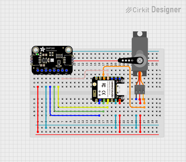
Explore Projects Built with esp32,a
Common Applications
- IoT devices and smart home systems
- Wireless sensor networks
- Wearable electronics
- Industrial automation and control
- Robotics and drones
- Prototyping and educational projects
Technical Specifications
Key Technical Details
- Processor: Dual-core Xtensa® 32-bit LX6 microprocessor
- Clock Speed: Up to 240 MHz
- Wi-Fi: 802.11 b/g/n (2.4 GHz)
- Bluetooth: v4.2 BR/EDR and BLE
- Flash Memory: 4 MB (varies by model)
- SRAM: 520 KB
- Operating Voltage: 3.0V to 3.6V
- GPIO Pins: 34 (multipurpose, including ADC, DAC, PWM, I2C, SPI, UART)
- ADC Channels: 18 (12-bit resolution)
- DAC Channels: 2 (8-bit resolution)
- Power Consumption: Ultra-low power modes available
- Operating Temperature: -40°C to 125°C
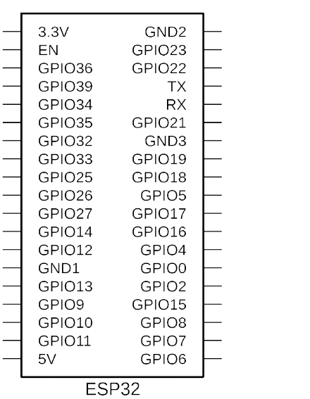
Pin Configuration and Descriptions
The ESP32 has multiple variants, but the following table outlines the general pin configuration for the ESP32-WROOM-32 module:
| Pin Name | Type | Description |
|---|---|---|
| GPIO0 | Input/Output | Used for boot mode selection during startup; can also be used as a general GPIO. |
| GPIO1 (TXD0) | Output | UART0 transmit pin; used for serial communication. |
| GPIO3 (RXD0) | Input | UART0 receive pin; used for serial communication. |
| GPIO2 | Input/Output | General-purpose GPIO; often used for onboard LED. |
| GPIO4 | Input/Output | General-purpose GPIO; supports PWM, ADC, and more. |
| GPIO5 | Input/Output | General-purpose GPIO; supports PWM, ADC, and more. |
| EN | Input | Chip enable pin; must be pulled high for normal operation. |
| 3V3 | Power | 3.3V power supply input. |
| GND | Power | Ground connection. |
| VIN | Power | Input voltage (5V) for onboard voltage regulator. |
Note: The ESP32 has many GPIO pins with multiple functions. Refer to the official datasheet for a complete pinout and alternate functions.
Usage Instructions
Using the ESP32 in a Circuit
Powering the ESP32:
- Connect the VIN pin to a 5V power source or use the 3V3 pin for a regulated 3.3V input.
- Ensure the GND pin is connected to the ground of your circuit.
Programming the ESP32:
- Use a USB-to-serial adapter or a development board with a built-in USB interface.
- Install the ESP32 board package in the Arduino IDE or use the Espressif IDF (IoT Development Framework) for advanced development.
Connecting Peripherals:
- Use the GPIO pins for connecting sensors, actuators, or other peripherals.
- Configure the pins in your code to match the required functionality (e.g., input, output, ADC, PWM).
Uploading Code:
- Select the correct board and port in the Arduino IDE.
- Press the "Upload" button to flash your code to the ESP32.
Example Code: Blinking an LED
The following example demonstrates how to blink an LED connected to GPIO2 of the ESP32:
// Define the GPIO pin where the LED is connected
const int ledPin = 2; // GPIO2 is often connected to the onboard LED

void setup() {
  pinMode(ledPin, OUTPUT); // Set GPIO2 as an output pin
}

void loop() {
  digitalWrite(ledPin, HIGH); // Turn the LED on
  delay(1000);               // Wait for 1 second
  digitalWrite(ledPin, LOW);  // Turn the LED off
  delay(1000);               // Wait for 1 second
}
Important Considerations
- Voltage Levels: The ESP32 operates at 3.3V logic levels. Avoid connecting 5V signals directly to its GPIO pins.
- Boot Mode: Ensure GPIO0 is pulled low during startup if you need to enter bootloader mode.
- Power Supply: Use a stable power source to avoid unexpected resets or instability.
Troubleshooting and FAQs
Common Issues
ESP32 Not Detected by the Computer:
- Ensure the correct USB driver is installed (e.g., CP210x or CH340).
- Check the USB cable for data transfer capability (some cables are power-only).
Code Upload Fails:
- Verify the correct board and port are selected in the Arduino IDE.
- Press and hold the "BOOT" button on the ESP32 while uploading the code.
Wi-Fi Connection Issues:
- Double-check the SSID and password in your code.
- Ensure the Wi-Fi network is within range and supports 2.4 GHz.
Random Resets or Instability:
- Use a stable power supply with sufficient current (at least 500 mA).
- Add decoupling capacitors near the power pins if necessary.
FAQs
Q1: Can the ESP32 be powered with 5V?
A1: Yes, the ESP32 can be powered via the VIN pin with 5V, which is regulated to 3.3V internally.
Q2: How do I use Bluetooth on the ESP32?
A2: The ESP32 supports both Bluetooth Classic and BLE. Use the BluetoothSerial or BLE libraries in the Arduino IDE to implement Bluetooth functionality.
Q3: Can I use the ESP32 with a 5V sensor?
A3: Yes, but you will need a level shifter to safely interface the 5V sensor with the 3.3V GPIO pins of the ESP32.
Q4: What is the maximum current draw of the ESP32?
A4: The ESP32 can draw up to 500 mA during peak operation (e.g., Wi-Fi transmission). Ensure your power supply can handle this.
By following this documentation, you can effectively integrate the ESP32 into your projects and troubleshoot common issues. For advanced features, refer to the official Espressif documentation.