How to Use nodemcu8266 lolin basboard: Examples, Pinouts, and Specs
Introduction
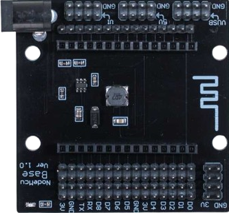
The NodeMCU ESP8266 Lolin Baseboard is a low-cost, open-source IoT platform based on the ESP8266 Wi-Fi module. It integrates a microcontroller with Wi-Fi capabilities, making it ideal for IoT applications. The board is designed to be easy to use, with a built-in USB interface for programming and power supply.
Explore Projects Built with nodemcu8266 lolin basboard


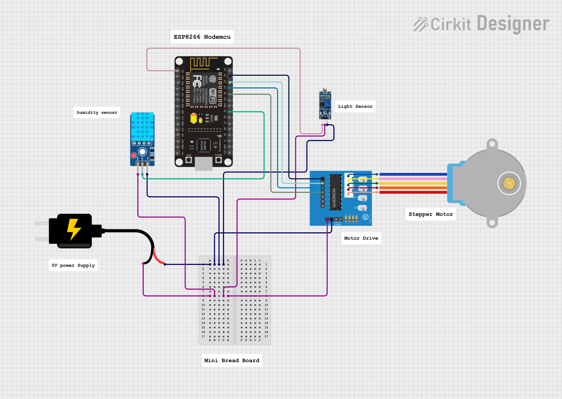

Explore Projects Built with nodemcu8266 lolin basboard
Common Applications and Use Cases
- Home automation
- IoT projects
- Wireless sensor networks
- Smart appliances
- Remote data logging
- Prototyping and development
Technical Specifications
Key Technical Details
| Specification | Value |
|---|---|
| Microcontroller | ESP8266 |
| Operating Voltage | 3.3V |
| Input Voltage | 4.5V - 10V (via VIN pin) |
| Digital I/O Pins | 11 |
| Analog Input Pins | 1 (10-bit ADC) |
| Flash Memory | 4MB |
| Clock Speed | 80MHz/160MHz |
| Wi-Fi Standard | 802.11 b/g/n |
| USB Interface | Micro-USB |
| Dimensions | 58mm x 31mm x 13mm |
Pin Configuration and Descriptions
| Pin | Name | Description |
|---|---|---|
| 1 | GND | Ground |
| 2 | VIN | External power supply (4.5V - 10V) |
| 3 | 3V3 | 3.3V output |
| 4 | EN | Chip enable (active high) |
| 5 | RST | Reset |
| 6 | D0 | GPIO16 |
| 7 | D1 | GPIO5 |
| 8 | D2 | GPIO4 |
| 9 | D3 | GPIO0 |
| 10 | D4 | GPIO2 |
| 11 | D5 | GPIO14 |
| 12 | D6 | GPIO12 |
| 13 | D7 | GPIO13 |
| 14 | D8 | GPIO15 |
| 15 | A0 | Analog input (0V - 3.3V) |
| 16 | TX | UART TX |
| 17 | RX | UART RX |
Usage Instructions
How to Use the Component in a Circuit
Powering the Board:
- Connect the board to your computer using a Micro-USB cable. This will provide power and allow for programming.
- Alternatively, you can power the board using an external power supply connected to the VIN and GND pins.
Programming the Board:
- Install the Arduino IDE and add the ESP8266 board support via the Board Manager.
- Select "NodeMCU 1.0 (ESP-12E Module)" from the Tools > Board menu.
- Write your code and upload it to the board using the "Upload" button.
Connecting Sensors and Actuators:
- Use the digital I/O pins (D0-D8) to connect sensors and actuators.
- Use the A0 pin for analog sensors (0V - 3.3V).
Important Considerations and Best Practices
- Voltage Levels: Ensure that all connected components operate at 3.3V logic levels to avoid damaging the board.
- Power Supply: When using an external power supply, ensure it provides a stable voltage within the specified range (4.5V - 10V).
- Wi-Fi Interference: Place the board away from sources of electromagnetic interference to maintain a stable Wi-Fi connection.
- Heat Dissipation: Avoid placing the board in enclosed spaces without ventilation to prevent overheating.
Example Code
Here is an example code to connect the NodeMCU ESP8266 Lolin Baseboard to an Arduino UNO and read data from a DHT11 temperature and humidity sensor.
#include <ESP8266WiFi.h>
#include <DHT.h>

#define DHTPIN D4     // DHT11 data pin connected to D4
#define DHTTYPE DHT11 // DHT 11

DHT dht(DHTPIN, DHTTYPE);

void setup() {
  Serial.begin(115200); // Initialize serial communication
  dht.begin();          // Initialize DHT sensor
}

void loop() {
  delay(2000); // Wait a few seconds between measurements

  float h = dht.readHumidity();    // Read humidity
  float t = dht.readTemperature(); // Read temperature in Celsius

  // Check if any reads failed and exit early (to try again).
  if (isnan(h) || isnan(t)) {
    Serial.println("Failed to read from DHT sensor!");
    return;
  }

  Serial.print("Humidity: ");
  Serial.print(h);
  Serial.print(" %\t");
  Serial.print("Temperature: ");
  Serial.print(t);
  Serial.println(" *C ");
}
Troubleshooting and FAQs
Common Issues Users Might Face
Board Not Detected by Computer:
- Ensure the USB cable is properly connected and is not damaged.
- Install the necessary USB drivers for the NodeMCU board.
Upload Failures:
- Check the selected board and port in the Arduino IDE.
- Press and hold the "Flash" button on the board while uploading the code.
Wi-Fi Connection Issues:
- Verify the SSID and password in your code.
- Ensure the Wi-Fi network is within range and not experiencing interference.
Solutions and Tips for Troubleshooting
- Serial Monitor: Use the Serial Monitor in the Arduino IDE to print debug messages and diagnose issues.
- Power Supply: Ensure the board is receiving a stable power supply. Unstable power can cause unexpected behavior.
- Resetting the Board: If the board becomes unresponsive, press the "RST" button to reset it.
By following this documentation, users should be able to effectively utilize the NodeMCU ESP8266 Lolin Baseboard in their projects, troubleshoot common issues, and implement best practices for optimal performance.