How to Use STEPPER Drivers Modular: Examples, Pinouts, and Specs
Introduction
Stepper drivers are electronic modules that serve as the interface between a microcontroller or motion controller and a stepper motor. They are essential components in precision motion control applications such as CNC machines, 3D printers, and robotics. These drivers interpret digital step and direction signals from the controller and translate them into controlled motor coil energization sequences, enabling precise control of the motor's position, speed, and torque.
Explore Projects Built with STEPPER Drivers Modular
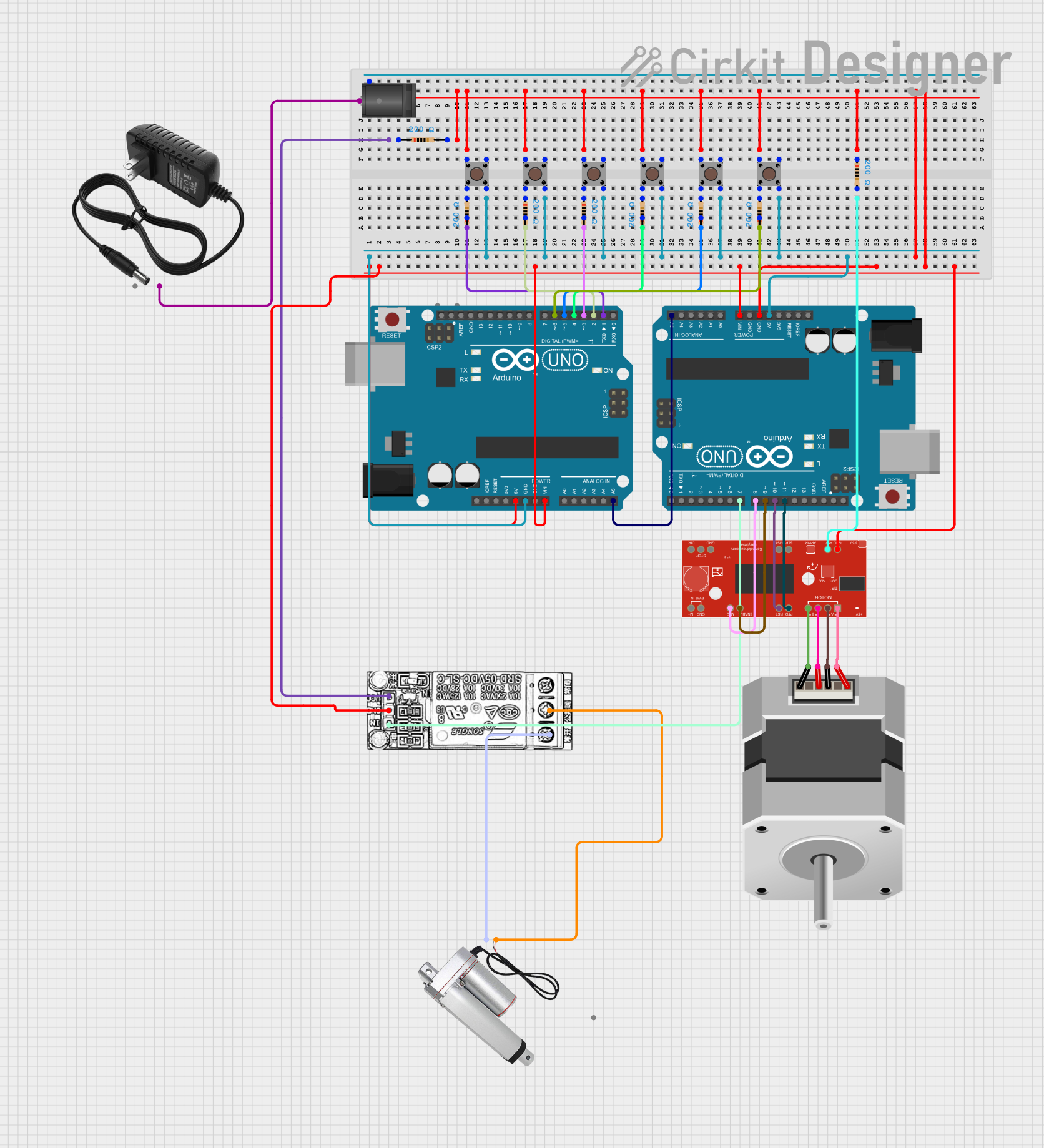

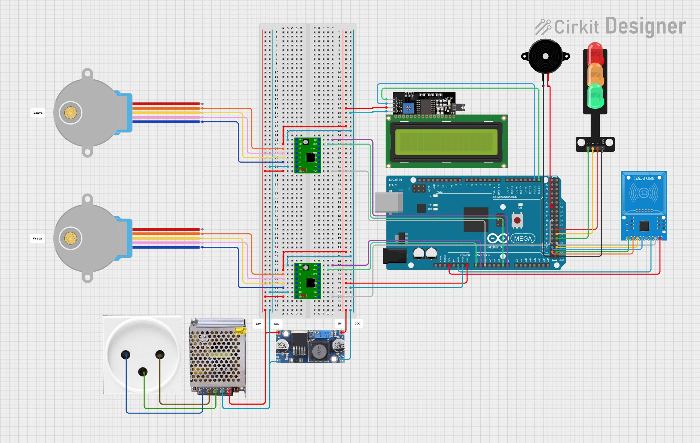

Explore Projects Built with STEPPER Drivers Modular
Common Applications and Use Cases
- CNC machines for cutting, drilling, or milling
- 3D printers for layer-by-layer construction
- Robotic arms for precise movement and positioning
- X-Y tables for laser cutting or plotting
- Automated camera tracking systems
Technical Specifications
Key Technical Details
- Input Voltage Range: Typically 8V to 45V (varies by model)
- Output Current: Up to 4A per phase (varies by model)
- Microstepping: Full, 1/2, 1/4, 1/8, 1/16, 1/32 steps (model dependent)
- Logic Input Voltage: 3.3V to 5V compatible
- Thermal Overload Protection: Yes (in most models)
- Short Circuit Protection: Yes (in most models)
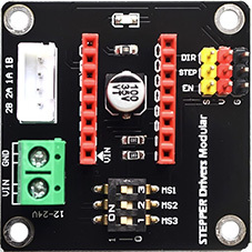
Pin Configuration and Descriptions
| Pin Name | Description |
|---|---|
| VMOT | Motor supply voltage (8V-45V) |
| GND | Ground connection |
| 2B, 2A | Motor coil connections for one phase |
| 1A, 1B | Motor coil connections for the other phase |
| VDD | Logic supply voltage (3.3V-5V) |
| GND | Logic ground connection |
| STEP | Step input (pulse to move one step) |
| DIR | Direction input (logic level sets direction) |
| EN | Enable input (logic low to enable driver) |
| MS1, MS2, MS3 | Microstepping resolution selection pins |
| RESET | Resets the driver (active low) |
| SLEEP | Puts driver into low power sleep mode (active low) |
Usage Instructions
How to Use the Component in a Circuit
Power Connections:
- Connect the motor power supply to VMOT and GND.
- Connect the logic power supply to VDD and GND.
Motor Connections:
- Connect the stepper motor coils to the 1A, 1B, 2A, and 2B pins.
Control Connections:
- Connect the STEP and DIR pins to the digital outputs of the microcontroller.
- Optionally, connect the EN, MS1, MS2, MS3, RESET, and SLEEP pins as required.
Microcontroller Interface:
- Use digital write operations to control the STEP and DIR pins.
- Use digital write operations to set the microstepping resolution with MS1, MS2, and MS3.
Important Considerations and Best Practices
- Ensure the power supply voltage and current ratings are within the specifications of the stepper driver.
- Use appropriate decoupling capacitors close to the VMOT and VDD pins to minimize voltage spikes.
- Avoid disconnecting the motor while the driver is powered to prevent damage.
- Set the current limit according to the motor's specifications to avoid overheating.
- Use heat sinks if operating at high currents for extended periods.
Example Code for Arduino UNO
// Define the stepper motor control pins
#define STEP_PIN 2
#define DIR_PIN 3

void setup() {
  // Set the motor control pins as outputs
  pinMode(STEP_PIN, OUTPUT);
  pinMode(DIR_PIN, OUTPUT);
}

void loop() {
  // Set the motor direction
  digitalWrite(DIR_PIN, HIGH); // Set to LOW to change direction

  // Move the motor one step
  digitalWrite(STEP_PIN, HIGH);
  delayMicroseconds(1000); // Adjust delay for speed control
  digitalWrite(STEP_PIN, LOW);
  delayMicroseconds(1000); // Adjust delay for speed control
}
Troubleshooting and FAQs
Common Issues Users Might Face
- Motor not moving: Check power supply, wiring, and ensure the enable pin is set correctly.
- Motor stalling or skipping steps: Adjust current limit, check for mechanical obstructions, or reduce speed.
- Overheating: Ensure proper current settings and use heat sinks if necessary.
Solutions and Tips for Troubleshooting
- Check connections: Verify all connections are secure and correctly wired.
- Test power supply: Ensure the power supply is delivering the correct voltage and current.
- Adjust current limit: Use the potentiometer on the driver to set the current limit to match the motor's specifications.
- Use diagnostic LEDs: Some drivers have LEDs that indicate power, step, and fault conditions.
FAQs
Q: Can I run the stepper motor at its maximum rated current? A: It's recommended to run the motor slightly below its maximum rated current to ensure longevity and prevent overheating.
Q: How do I change the microstepping resolution? A: Adjust the logic levels on the MS1, MS2, and MS3 pins according to the driver's datasheet.
Q: What should I do if the motor is making noise but not moving? A: This could be due to incorrect microstepping settings or a mechanical issue. Check the microstepping pins and ensure there are no mechanical blockages.