Cirkit Designer Logo
Cirkit Designer
Your all-in-one circuit design IDE
Home / 
Component Documentation

How to Use GY-MAX30102: Examples, Pinouts, and Specs

Image of GY-MAX30102
Cirkit Designer LogoDesign with GY-MAX30102 in Cirkit Designer

Introduction

The GY-MAX30102 is a heart rate and SpO2 sensor module designed for non-invasive health monitoring. It utilizes photoplethysmography (PPG) technology to measure blood oxygen saturation (SpO2) and heart rate by detecting changes in blood volume through light absorption. The module is built around the MAX30102 sensor chip, which integrates red and infrared LEDs, a photodetector, and an ambient light rejection circuit for precise measurements.

This module is widely used in wearable health devices, fitness trackers, and medical monitoring systems. Its compact size and low power consumption make it ideal for portable applications.

Explore Projects Built with GY-MAX30102

Use Cirkit Designer to design, explore, and prototype these projects online. Some projects support real-time simulation. Click "Open Project" to start designing instantly!
Satellite-Based Timing and Navigation System with SDR and Atomic Clock Synchronization
Image of GPS 시스템 측정 구성도_Confirm: A project utilizing GY-MAX30102 in a practical application
This circuit appears to be a complex system involving power supply management, GPS and timing synchronization, and data communication. It includes a SI-TEX G1 Satellite Compass for GPS data, an XHTF1021 Atomic Rubidium Clock for precise timing, and Ettus USRP B200 units for software-defined radio communication. Power is supplied through various SMPS units and distributed via terminal blocks and DC jacks. Data communication is facilitated by Beelink MINI S12 N95 computers, RS232 splitters, and a 1000BASE-T Media Converter for network connectivity. RF Directional Couplers are used to interface antennas with the USRP units, and the entire system is likely contained within cases for protection and organization.
Cirkit Designer LogoOpen Project in Cirkit Designer
Battery-Powered Health Monitoring System with Nucleo WB55RG and OLED Display
Image of Pulsefex: A project utilizing GY-MAX30102 in a practical application
This circuit is a multi-sensor data acquisition system that uses a Nucleo WB55RG microcontroller to interface with a digital temperature sensor (TMP102), a pulse oximeter and heart-rate sensor (MAX30102), and a 0.96" OLED display via I2C. Additionally, it includes a Sim800l module for GSM communication, powered by a 3.7V LiPo battery.
Cirkit Designer LogoOpen Project in Cirkit Designer
Multi-Channel Load Cell Measurement System with JYS60 Amplifiers and DAQ Integration
Image of Load Cell Circuit: A project utilizing GY-MAX30102 in a practical application
This is a multi-channel load cell measurement system with several JYS60 amplifiers connected to load cells for weight or force sensing. The amplified signals are directed to a DAQ system for data capture, and power is supplied through a barrel jack. Grounding is achieved via an AdaGator Side Black component.
Cirkit Designer LogoOpen Project in Cirkit Designer
Battery-Powered RC Car with Massive RC MDEx and MDD10A Motor Driver
Image of Massive RC MDEx: A project utilizing GY-MAX30102 in a practical application
This circuit is a remote-controlled motor driver system powered by a LiPo battery. It uses a Massive RC MDEx microcontroller to control an MDD10A dual motor driver, which in turn drives two GM25 DC motors. The R6FG receiver receives remote control signals to manage the motor directions and speeds.
Cirkit Designer LogoOpen Project in Cirkit Designer

Explore Projects Built with GY-MAX30102

Use Cirkit Designer to design, explore, and prototype these projects online. Some projects support real-time simulation. Click "Open Project" to start designing instantly!
Image of GPS 시스템 측정 구성도_Confirm: A project utilizing GY-MAX30102 in a practical application
Satellite-Based Timing and Navigation System with SDR and Atomic Clock Synchronization
This circuit appears to be a complex system involving power supply management, GPS and timing synchronization, and data communication. It includes a SI-TEX G1 Satellite Compass for GPS data, an XHTF1021 Atomic Rubidium Clock for precise timing, and Ettus USRP B200 units for software-defined radio communication. Power is supplied through various SMPS units and distributed via terminal blocks and DC jacks. Data communication is facilitated by Beelink MINI S12 N95 computers, RS232 splitters, and a 1000BASE-T Media Converter for network connectivity. RF Directional Couplers are used to interface antennas with the USRP units, and the entire system is likely contained within cases for protection and organization.
Cirkit Designer LogoOpen Project in Cirkit Designer
Image of Pulsefex: A project utilizing GY-MAX30102 in a practical application
Battery-Powered Health Monitoring System with Nucleo WB55RG and OLED Display
This circuit is a multi-sensor data acquisition system that uses a Nucleo WB55RG microcontroller to interface with a digital temperature sensor (TMP102), a pulse oximeter and heart-rate sensor (MAX30102), and a 0.96" OLED display via I2C. Additionally, it includes a Sim800l module for GSM communication, powered by a 3.7V LiPo battery.
Cirkit Designer LogoOpen Project in Cirkit Designer
Image of Load Cell Circuit: A project utilizing GY-MAX30102 in a practical application
Multi-Channel Load Cell Measurement System with JYS60 Amplifiers and DAQ Integration
This is a multi-channel load cell measurement system with several JYS60 amplifiers connected to load cells for weight or force sensing. The amplified signals are directed to a DAQ system for data capture, and power is supplied through a barrel jack. Grounding is achieved via an AdaGator Side Black component.
Cirkit Designer LogoOpen Project in Cirkit Designer
Image of Massive RC MDEx: A project utilizing GY-MAX30102 in a practical application
Battery-Powered RC Car with Massive RC MDEx and MDD10A Motor Driver
This circuit is a remote-controlled motor driver system powered by a LiPo battery. It uses a Massive RC MDEx microcontroller to control an MDD10A dual motor driver, which in turn drives two GM25 DC motors. The R6FG receiver receives remote control signals to manage the motor directions and speeds.
Cirkit Designer LogoOpen Project in Cirkit Designer

Technical Specifications

  • Sensor Chip: MAX30102
  • Supply Voltage: 1.8V (internal) and 3.3V (external)
  • Operating Current: 600 µA (typical)
  • Standby Current: 0.7 µA
  • Communication Protocol: I²C (Inter-Integrated Circuit)
  • I²C Address: 0x57 (default)
  • LED Wavelengths:
    • Red: 660 nm
    • Infrared: 880 nm
  • Operating Temperature: -40°C to +85°C
  • Dimensions: 14mm x 14mm

Pin Configuration and Descriptions

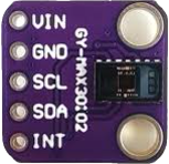
The GY-MAX30102 module has six pins. Below is the pinout and description:

Pin Name Description
1 VIN Power supply input (3.3V to 5V). Connect to the 3.3V or 5V pin of your microcontroller.
2 GND Ground. Connect to the ground of your circuit.
3 SCL I²C clock line. Connect to the SCL pin of your microcontroller.
4 SDA I²C data line. Connect to the SDA pin of your microcontroller.
5 INT Interrupt pin. Optional, used for event-driven applications.
6 IRD Infrared LED driver pin. Typically not used in standard applications.

Usage Instructions

How to Use the GY-MAX30102 in a Circuit

  1. Power the Module: Connect the VIN pin to a 3.3V or 5V power source and the GND pin to ground.
  2. Connect I²C Lines: Connect the SCL and SDA pins to the corresponding I²C pins on your microcontroller. Use pull-up resistors (typically 4.7kΩ) if your microcontroller does not have internal pull-ups.
  3. Optional Connections: The INT pin can be connected to a GPIO pin on your microcontroller for interrupt-driven applications, but it is not required for basic functionality.
  4. Install Libraries: If using an Arduino, install the "SparkFun MAX3010x Pulse and Proximity Sensor Library" from the Arduino Library Manager.
  5. Write Code: Use the library functions to initialize the sensor, read heart rate, and measure SpO2.

Important Considerations and Best Practices

  • Ensure the sensor is placed in contact with the skin for accurate readings.
  • Avoid direct exposure to ambient light, as it may interfere with measurements.
  • Use a stable power supply to minimize noise in the readings.
  • The module is sensitive to motion; keep it steady during measurements for better accuracy.

Example Code for Arduino UNO

Below is an example of how to use the GY-MAX30102 with an Arduino UNO:

#include <Wire.h>
#include "MAX30105.h" // Include the SparkFun MAX3010x library

MAX30105 particleSensor; // Create an instance of the sensor

void setup() {
  Serial.begin(9600); // Initialize serial communication
  Serial.println("Initializing GY-MAX30102...");

  // Initialize the sensor
  if (!particleSensor.begin()) {
    Serial.println("MAX30102 not detected. Check connections.");
    while (1); // Halt execution if the sensor is not found
  }

  // Configure the sensor
  particleSensor.setup(); // Use default settings
  particleSensor.setPulseAmplitudeRed(0x0A); // Set red LED brightness
  particleSensor.setPulseAmplitudeIR(0x0A);  // Set IR LED brightness
}

void loop() {
  // Read data from the sensor
  long redValue = particleSensor.getRed(); // Get red light reading
  long irValue = particleSensor.getIR();   // Get IR light reading

  // Print the readings to the serial monitor
  Serial.print("Red: ");
  Serial.print(redValue);
  Serial.print(" IR: ");
  Serial.println(irValue);

  delay(100); // Wait 100ms before the next reading
}

Troubleshooting and FAQs

Common Issues and Solutions

  1. Sensor Not Detected:

    • Cause: Incorrect wiring or I²C address mismatch.
    • Solution: Double-check the connections and ensure the I²C address is set to 0x57 in your code.
  2. Inaccurate Readings:

    • Cause: Poor contact with the skin or excessive ambient light.
    • Solution: Ensure the sensor is in direct contact with the skin and shield it from ambient light.
  3. No Data Output:

    • Cause: Library not installed or incorrect initialization.
    • Solution: Verify that the SparkFun MAX3010x library is installed and the sensor is initialized correctly in the code.
  4. High Noise in Readings:

    • Cause: Unstable power supply or excessive motion.
    • Solution: Use a stable power source and minimize motion during measurements.

FAQs

  • Can the GY-MAX30102 measure SpO2 and heart rate simultaneously? Yes, the module can measure both parameters simultaneously using the red and IR LEDs.

  • What is the maximum I²C clock speed supported? The MAX30102 supports I²C clock speeds up to 400kHz.

  • Can I use the GY-MAX30102 with a 5V microcontroller? Yes, the module has an onboard voltage regulator, allowing it to work with 3.3V and 5V systems.

  • Is the module suitable for continuous monitoring? Yes, but ensure proper heat dissipation and power management for long-term use.