Cirkit Designer Logo
Cirkit Designer
Your all-in-one circuit design IDE
Home / 
Component Documentation

How to Use Wiznet Pico: Examples, Pinouts, and Specs

Image of Wiznet Pico
Cirkit Designer LogoDesign with Wiznet Pico in Cirkit Designer

Introduction

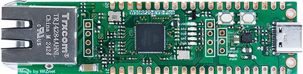
The Wiznet Pico (W55RP20-EVB-PICO) is a compact, low-power Ethernet module designed for Internet of Things (IoT) applications. It features a built-in TCP/IP stack, enabling seamless integration with microcontrollers for reliable and efficient network connectivity. This module is based on the W5500 Ethernet controller and is compatible with the Raspberry Pi Pico form factor, making it an excellent choice for developers looking to add Ethernet functionality to their projects.

Explore Projects Built with Wiznet Pico

Use Cirkit Designer to design, explore, and prototype these projects online. Some projects support real-time simulation. Click "Open Project" to start designing instantly!
Wi-Fi Controlled RGB Lighting with Raspberry Pi Pico W
Image of Smart Home Automation 1: A project utilizing Wiznet Pico in a practical application
This circuit features a Raspberry Pi Pico W microcontroller connected to an RGB LED through GPIO pins GP17, GP18, and GP19 for controlling the blue, green, and red channels, respectively. A resistor is connected between the 3V3 OUT pin of the Pico and the common cathode of the RGB LED to limit the current. The embedded code suggests the Pico W is configured for Wi-Fi connectivity and MQTT communication to control the LED and possibly other peripherals not shown in the circuit, with additional functionality for sensor monitoring and display output.
Cirkit Designer LogoOpen Project in Cirkit Designer
Raspberry Pi Pico-Based Navigation Assistant with Bluetooth and GPS
Image of sat_dish: compass example: A project utilizing Wiznet Pico in a practical application
This circuit features a Raspberry Pi Pico microcontroller interfaced with an HC-05 Bluetooth module for wireless communication, an HMC5883L compass module for magnetic field measurement, and a GPS NEO 6M module for location tracking. The Pico is configured to communicate with the HC-05 via serial connection (TX/RX), with the compass module via I2C (SCL/SDA), and with the GPS module via serial (TX/RX). Common power (VCC) and ground (GND) lines are shared among all modules, indicating a unified power system.
Cirkit Designer LogoOpen Project in Cirkit Designer
Raspberry Pi Pico W-Based Smart Home Automation System with Motion Detection and Environmental Monitoring
Image of Smart Home Automation 1: A project utilizing Wiznet Pico in a practical application
This circuit features a Raspberry Pi Pico W microcontroller connected to various sensors and actuators, including a DHT11 temperature and humidity sensor, an RCWL-0516 microwave radar motion sensor, a photocell (LDR) with a resistor for light detection, and a two-channel relay controlling a bulb and a fan. The microcontroller runs code to monitor environmental conditions and motion, displaying information on an LCD and allowing remote control via MQTT messages over Wi-Fi. It supports both automatic sensor-based operation and remote app control, with pushbuttons to switch between modes.
Cirkit Designer LogoOpen Project in Cirkit Designer
Raspberry Pi Pico and ESP32 Wi-Fi Controlled Sensor Interface
Image of pico_esp32: A project utilizing Wiznet Pico in a practical application
This circuit integrates a Raspberry Pi Pico and an ESP32 Wroom Dev Kit, interconnected through various GPIO pins and resistors, to enable communication and control between the two microcontrollers. The ESP32 is powered by a 3.3V supply and shares ground with the Raspberry Pi Pico, while specific GPIO pins are used for data exchange. The provided code sketches for the Raspberry Pi Pico suggest a framework for further development of the system's functionality.
Cirkit Designer LogoOpen Project in Cirkit Designer

Explore Projects Built with Wiznet Pico

Use Cirkit Designer to design, explore, and prototype these projects online. Some projects support real-time simulation. Click "Open Project" to start designing instantly!
Image of Smart Home Automation 1: A project utilizing Wiznet Pico in a practical application
Wi-Fi Controlled RGB Lighting with Raspberry Pi Pico W
This circuit features a Raspberry Pi Pico W microcontroller connected to an RGB LED through GPIO pins GP17, GP18, and GP19 for controlling the blue, green, and red channels, respectively. A resistor is connected between the 3V3 OUT pin of the Pico and the common cathode of the RGB LED to limit the current. The embedded code suggests the Pico W is configured for Wi-Fi connectivity and MQTT communication to control the LED and possibly other peripherals not shown in the circuit, with additional functionality for sensor monitoring and display output.
Cirkit Designer LogoOpen Project in Cirkit Designer
Image of sat_dish: compass example: A project utilizing Wiznet Pico in a practical application
Raspberry Pi Pico-Based Navigation Assistant with Bluetooth and GPS
This circuit features a Raspberry Pi Pico microcontroller interfaced with an HC-05 Bluetooth module for wireless communication, an HMC5883L compass module for magnetic field measurement, and a GPS NEO 6M module for location tracking. The Pico is configured to communicate with the HC-05 via serial connection (TX/RX), with the compass module via I2C (SCL/SDA), and with the GPS module via serial (TX/RX). Common power (VCC) and ground (GND) lines are shared among all modules, indicating a unified power system.
Cirkit Designer LogoOpen Project in Cirkit Designer
Image of Smart Home Automation 1: A project utilizing Wiznet Pico in a practical application
Raspberry Pi Pico W-Based Smart Home Automation System with Motion Detection and Environmental Monitoring
This circuit features a Raspberry Pi Pico W microcontroller connected to various sensors and actuators, including a DHT11 temperature and humidity sensor, an RCWL-0516 microwave radar motion sensor, a photocell (LDR) with a resistor for light detection, and a two-channel relay controlling a bulb and a fan. The microcontroller runs code to monitor environmental conditions and motion, displaying information on an LCD and allowing remote control via MQTT messages over Wi-Fi. It supports both automatic sensor-based operation and remote app control, with pushbuttons to switch between modes.
Cirkit Designer LogoOpen Project in Cirkit Designer
Image of pico_esp32: A project utilizing Wiznet Pico in a practical application
Raspberry Pi Pico and ESP32 Wi-Fi Controlled Sensor Interface
This circuit integrates a Raspberry Pi Pico and an ESP32 Wroom Dev Kit, interconnected through various GPIO pins and resistors, to enable communication and control between the two microcontrollers. The ESP32 is powered by a 3.3V supply and shares ground with the Raspberry Pi Pico, while specific GPIO pins are used for data exchange. The provided code sketches for the Raspberry Pi Pico suggest a framework for further development of the system's functionality.
Cirkit Designer LogoOpen Project in Cirkit Designer

Common Applications and Use Cases

  • IoT devices requiring wired Ethernet connectivity
  • Home automation systems
  • Industrial monitoring and control
  • Network-enabled sensors and actuators
  • Educational and prototyping projects

Technical Specifications

The following table outlines the key technical details of the Wiznet Pico module:

Parameter Specification
Ethernet Controller W5500
Network Interface 10/100 Mbps Ethernet
Operating Voltage 3.3V
Power Consumption ~132 mA (typical)
Communication Interface SPI (Serial Peripheral Interface)
Dimensions 51mm x 21mm
Operating Temperature -40°C to +85°C
Built-in TCP/IP Stack Yes
Supported Protocols TCP, UDP, ICMP, IPv4, ARP, IGMP, PPPoE

Pin Configuration and Descriptions

The Wiznet Pico module has a pinout compatible with the Raspberry Pi Pico form factor. Below is the pin configuration:

Pin Name Description
1 GND Ground
2 3V3 3.3V Power Supply
3 SPI_MOSI SPI Master Out Slave In
4 SPI_MISO SPI Master In Slave Out
5 SPI_SCK SPI Clock
6 SPI_CS SPI Chip Select
7 INT Interrupt Pin (Active Low)
8 RST Reset Pin (Active Low)
9 TX+ Ethernet Transmit Positive
10 TX- Ethernet Transmit Negative
11 RX+ Ethernet Receive Positive
12 RX- Ethernet Receive Negative

Usage Instructions

How to Use the Wiznet Pico in a Circuit

  1. Power Supply: Connect the 3.3V pin to a regulated 3.3V power source and GND to ground.
  2. SPI Communication: Connect the SPI pins (MOSI, MISO, SCK, and CS) to the corresponding SPI pins on your microcontroller.
  3. Ethernet Connection: Attach an Ethernet cable to the RJ45 connector on the module.
  4. Interrupt and Reset: Optionally, connect the INT pin to monitor interrupts and the RST pin for hardware resets.

Important Considerations and Best Practices

  • Ensure the SPI clock speed does not exceed 80 MHz for reliable communication.
  • Use proper decoupling capacitors near the power pins to minimize noise.
  • Avoid hot-plugging the Ethernet cable to prevent damage to the module.
  • Use a stable 3.3V power supply to ensure consistent operation.

Example Code for Arduino UNO

Below is an example of how to use the Wiznet Pico with an Arduino UNO to establish a basic Ethernet connection:

#include <SPI.h>
#include <Ethernet.h>

// MAC address for the Ethernet module
byte mac[] = { 0xDE, 0xAD, 0xBE, 0xEF, 0xFE, 0xED };

// IP address for the device (adjust as needed)
IPAddress ip(192, 168, 1, 177);

// Initialize the Ethernet server on port 80
EthernetServer server(80);

void setup() {
  // Start the serial communication for debugging
  Serial.begin(9600);

  // Initialize the Ethernet module
  if (Ethernet.begin(mac) == 0) {
    Serial.println("Failed to configure Ethernet using DHCP");
    // Use static IP if DHCP fails
    Ethernet.begin(mac, ip);
  }

  // Start the server
  server.begin();
  Serial.print("Server is at ");
  Serial.println(Ethernet.localIP());
}

void loop() {
  // Listen for incoming clients
  EthernetClient client = server.available();
  if (client) {
    Serial.println("New client connected");
    while (client.connected()) {
      if (client.available()) {
        char c = client.read();
        Serial.write(c); // Echo the received data to the serial monitor
        // Respond to the client
        client.println("Hello from Wiznet Pico!");
      }
    }
    client.stop();
    Serial.println("Client disconnected");
  }
}

Troubleshooting and FAQs

Common Issues and Solutions

  1. Ethernet Not Connecting

    • Cause: Incorrect SPI connections or faulty Ethernet cable.
    • Solution: Double-check the SPI wiring and ensure the Ethernet cable is functional.
  2. Module Not Responding

    • Cause: Insufficient power supply or incorrect reset sequence.
    • Solution: Verify the 3.3V power supply and ensure the RST pin is properly connected.
  3. Slow Network Performance

    • Cause: High SPI clock speed or network congestion.
    • Solution: Reduce the SPI clock speed and check the network environment.

FAQs

  1. Can the Wiznet Pico work with 5V microcontrollers?

    • Yes, but you must use level shifters to convert the 5V logic to 3.3V for SPI communication.
  2. Does the module support IPv6?

    • No, the Wiznet Pico supports only IPv4.
  3. Can I use the module with platforms other than Arduino?

    • Yes, the module is compatible with any platform that supports SPI communication, such as Raspberry Pi, STM32, and ESP32.
  4. What is the maximum cable length for Ethernet?

    • The module supports standard Ethernet cable lengths of up to 100 meters (328 feet).