How to Use WPME-FDSM : Examples, Pinouts, and Specs
Introduction
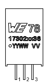
The WPME-FDSM, manufactured by Würth (Part ID: 173020336), is a versatile electronic component designed for frequency division and signal modulation. It is widely used in communication systems where precise timing and frequency control are critical. This component is particularly suitable for applications such as radio frequency (RF) systems, signal processing, and digital communication networks.
Explore Projects Built with WPME-FDSM


Explore Projects Built with WPME-FDSM
Common Applications and Use Cases
- Frequency division in RF communication systems
- Signal modulation for digital and analog communication
- Timing synchronization in networked systems
- Clock signal generation and distribution
- Applications requiring low phase noise and high stability
Technical Specifications
Key Technical Details
| Parameter | Value |
|---|---|
| Manufacturer | Würth |
| Part ID | 173020336 |
| Operating Voltage Range | 3.3V to 5V |
| Operating Current | 10 mA (typical) |
| Frequency Range | 1 MHz to 100 MHz |
| Modulation Type | Frequency Division and Modulation |
| Phase Noise | -120 dBc/Hz at 10 kHz offset |
| Operating Temperature | -40°C to +85°C |
| Package Type | SMD (Surface-Mount Device) |
Pin Configuration and Descriptions
The WPME-FDSM is a surface-mount device with 8 pins. The pin configuration is as follows:
| Pin Number | Pin Name | Description |
|---|---|---|
| 1 | VCC | Power supply input (3.3V to 5V) |
| 2 | GND | Ground connection |
| 3 | IN | Input signal for frequency division/modulation |
| 4 | OUT | Output signal after frequency division/modulation |
| 5 | CTRL1 | Control pin 1 for modulation settings |
| 6 | CTRL2 | Control pin 2 for frequency division settings |
| 7 | NC | No connection (leave unconnected) |
| 8 | NC | No connection (leave unconnected) |
Usage Instructions
How to Use the WPME-FDSM in a Circuit
- Power Supply: Connect the VCC pin to a stable power source within the range of 3.3V to 5V. Connect the GND pin to the ground of the circuit.
- Input Signal: Feed the input signal to the IN pin. Ensure the signal frequency is within the supported range (1 MHz to 100 MHz).
- Output Signal: The processed signal will be available at the OUT pin. Connect this pin to the desired load or subsequent stage in your circuit.
- Control Pins: Use CTRL1 and CTRL2 to configure the modulation and frequency division settings. Refer to the manufacturer's datasheet for specific control logic.
Important Considerations and Best Practices
- Decoupling Capacitors: Place a 0.1 µF ceramic capacitor close to the VCC pin to filter out noise and ensure stable operation.
- Signal Integrity: Use short and direct traces for the IN and OUT pins to minimize signal degradation.
- Thermal Management: Ensure adequate ventilation or heat dissipation if the component operates near its maximum temperature range.
- Unused Pins: Leave the NC pins unconnected to avoid interference.
Example: Using WPME-FDSM with Arduino UNO
The WPME-FDSM can be interfaced with an Arduino UNO for frequency division applications. Below is an example code snippet:
// Example: Using WPME-FDSM for frequency division with Arduino UNO
// Connect the IN pin of WPME-FDSM to pin 8 of Arduino UNO
// Connect the OUT pin of WPME-FDSM to an oscilloscope or other output device

const int inputPin = 8;  // Arduino pin connected to WPME-FDSM IN pin
const int controlPin1 = 9;  // Arduino pin connected to CTRL1
const int controlPin2 = 10; // Arduino pin connected to CTRL2

void setup() {
  pinMode(inputPin, OUTPUT);  // Set inputPin as output
  pinMode(controlPin1, OUTPUT);  // Set controlPin1 as output
  pinMode(controlPin2, OUTPUT);  // Set controlPin2 as output

  // Configure control pins for desired frequency division
  digitalWrite(controlPin1, HIGH);  // Example: Set CTRL1 to HIGH
  digitalWrite(controlPin2, LOW);   // Example: Set CTRL2 to LOW
}

void loop() {
  // Generate a square wave signal on inputPin
  digitalWrite(inputPin, HIGH);  // Set inputPin HIGH
  delayMicroseconds(10);         // Delay for 10 microseconds
  digitalWrite(inputPin, LOW);   // Set inputPin LOW
  delayMicroseconds(10);         // Delay for 10 microseconds
}
Troubleshooting and FAQs
Common Issues and Solutions
No Output Signal:
- Ensure the power supply voltage is within the specified range (3.3V to 5V).
- Verify that the input signal frequency is within the supported range (1 MHz to 100 MHz).
- Check the control pin configurations (CTRL1 and CTRL2) for proper settings.
Distorted Output Signal:
- Use short and direct traces for the IN and OUT pins to reduce signal degradation.
- Add decoupling capacitors near the VCC pin to filter out noise.
Overheating:
- Ensure the component is not operating beyond its maximum temperature range (-40°C to +85°C).
- Provide adequate ventilation or heat dissipation.
FAQs
Q1: Can the WPME-FDSM handle input signals below 1 MHz?
A1: No, the WPME-FDSM is designed to operate within the frequency range of 1 MHz to 100 MHz. Input signals outside this range may result in improper operation.
Q2: What happens if the NC pins are connected?
A2: The NC (No Connection) pins should be left unconnected. Connecting them may cause unexpected behavior or damage to the component.
Q3: Can the WPME-FDSM be used in high-temperature environments?
A3: The WPME-FDSM can operate within a temperature range of -40°C to +85°C. For environments exceeding this range, additional cooling measures are required.