How to Use Magnetic door Lock: Examples, Pinouts, and Specs

Introduction
A magnetic door lock, also known as a maglock, is an electronic locking device that uses an electromagnet to secure a door. When energized, the electromagnet creates a strong magnetic field that holds the door securely closed. When de-energized, the magnetic field is released, allowing the door to open freely. Magnetic door locks are widely used in access control systems due to their reliability, durability, and ease of integration with other electronic systems.
Explore Projects Built with Magnetic door Lock
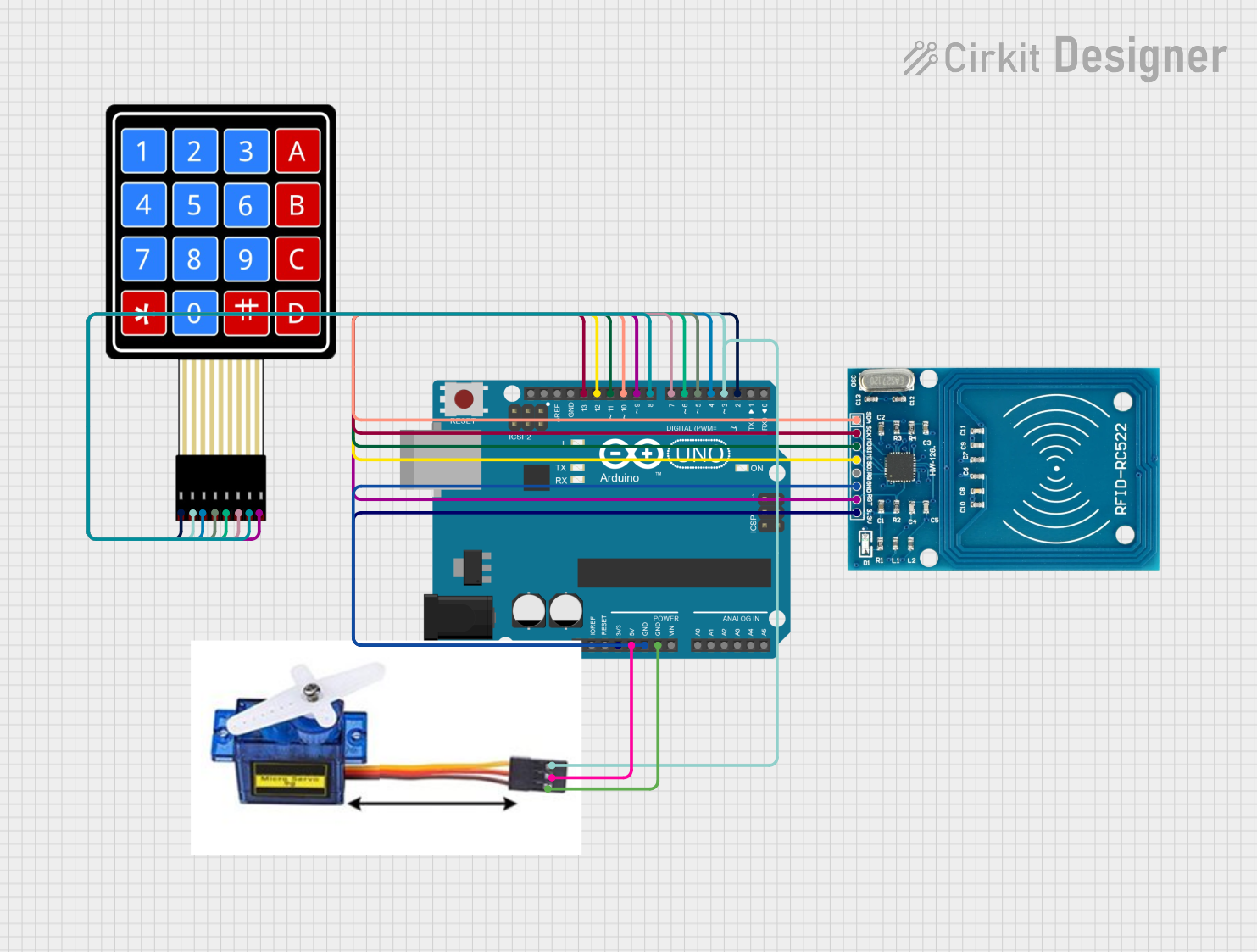
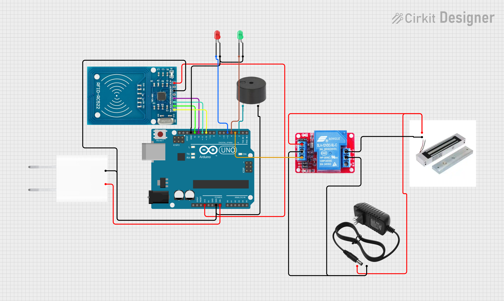
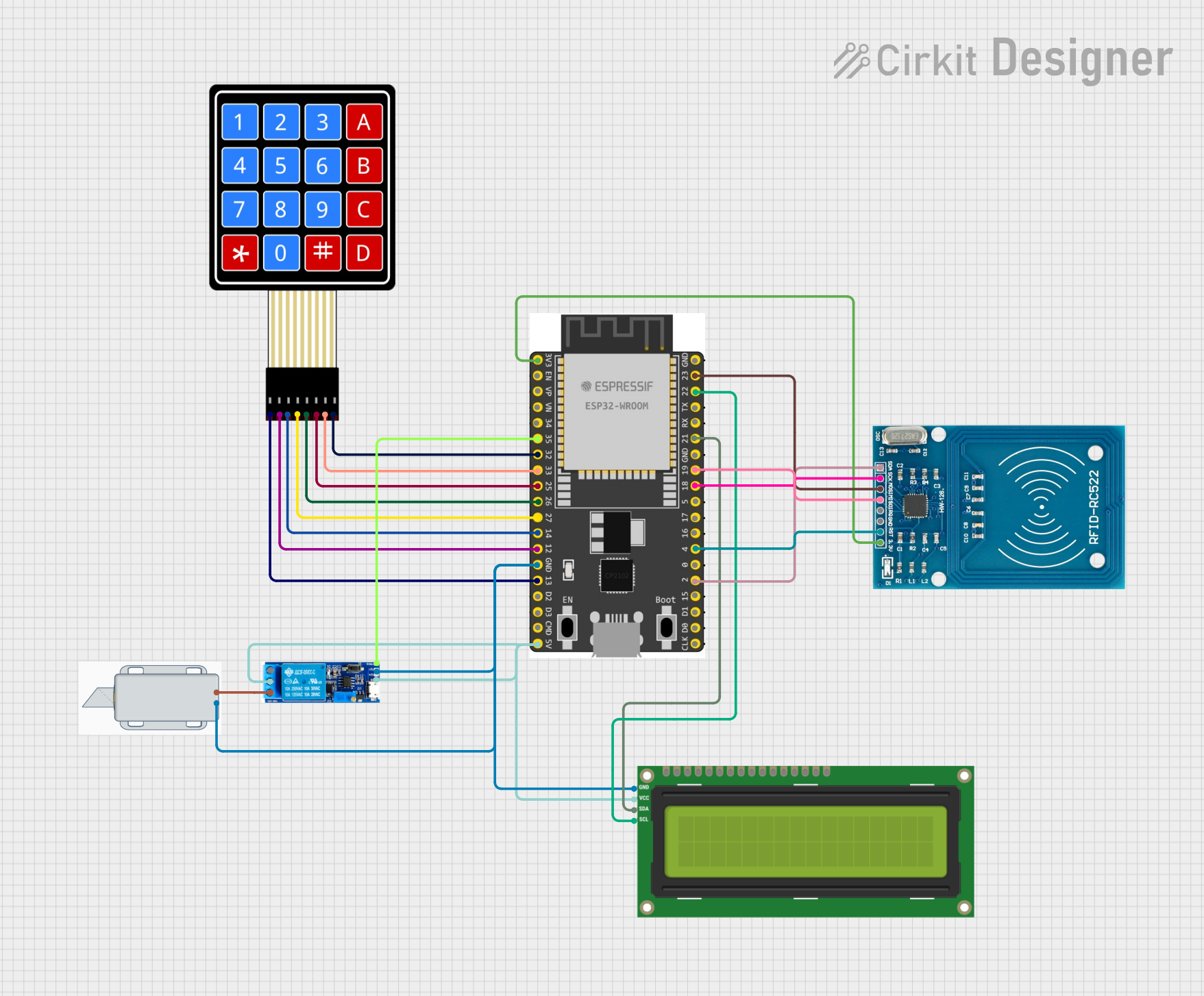
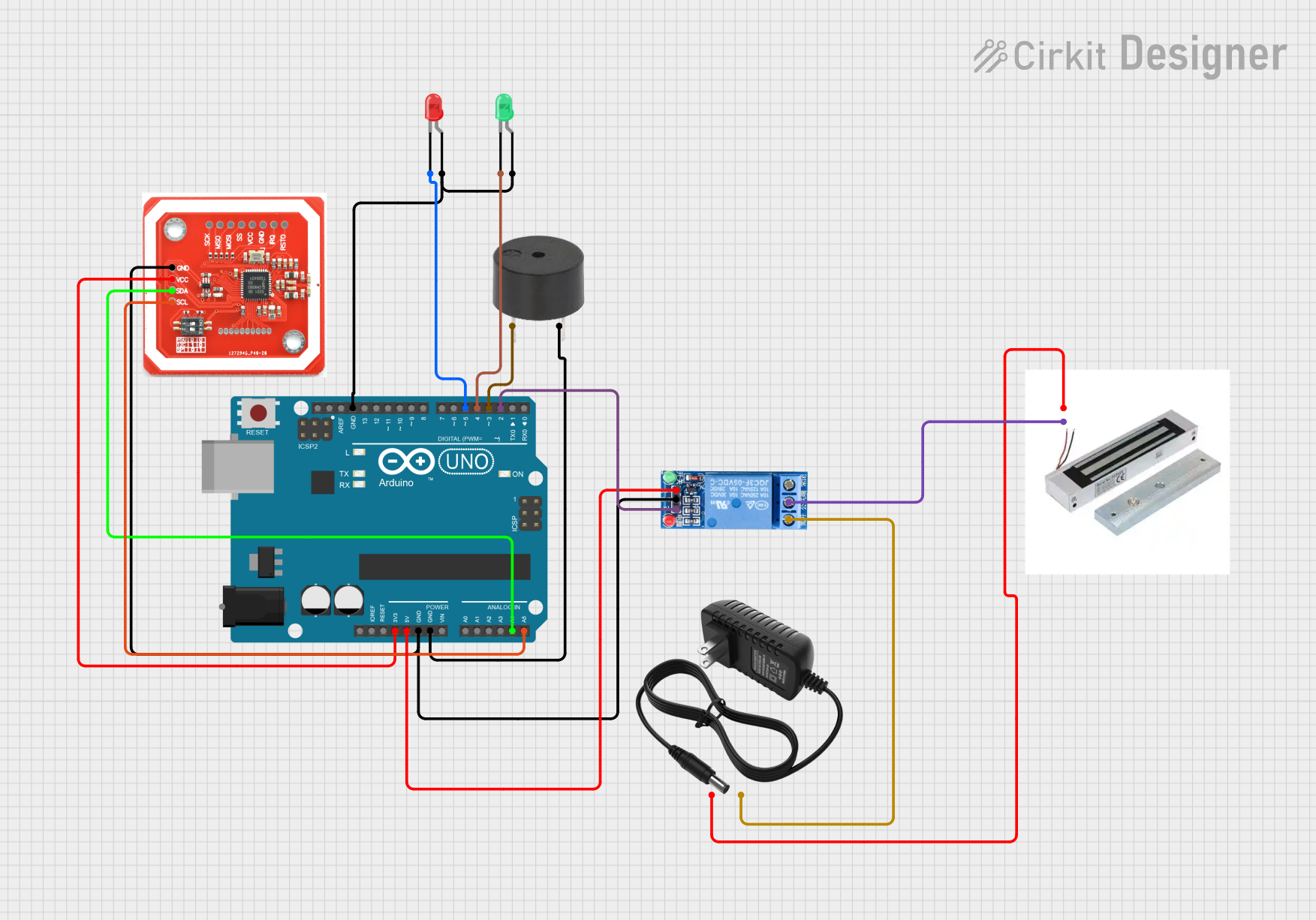
Explore Projects Built with Magnetic door Lock
Common Applications and Use Cases
- Office buildings and commercial spaces for access control
- Residential security systems
- Emergency exit doors with fail-safe functionality
- Automated doors in smart home systems
- Industrial facilities requiring controlled access
Technical Specifications
Below are the key technical details for a typical magnetic door lock:
| Parameter | Value |
|---|---|
| Operating Voltage | 12V DC or 24V DC (model-dependent) |
| Current Consumption | 0.3A to 0.5A (at 12V DC) |
| Holding Force | 300 lbs to 1200 lbs (model-dependent) |
| Lock Type | Fail-safe (unlocks when power is off) |
| Material | Aluminum housing, steel plate |
| Operating Temperature | -10°C to 55°C |
| Dimensions | Varies by model (e.g., 250mm x 48mm x 25mm) |
| Weight | Typically 2-5 kg |
Pin Configuration and Descriptions
Magnetic door locks typically have a simple wiring interface. Below is a table describing the common pin configuration:
| Pin/Terminal | Description |
|---|---|
| V+ | Positive power input (12V DC or 24V DC) |
| GND | Ground connection |
| NC (Normally Closed) | Optional connection for monitoring door status (closed) |
| NO (Normally Open) | Optional connection for monitoring door status (open) |
Usage Instructions
How to Use the Component in a Circuit
- Power Supply: Connect the V+ terminal to a 12V DC or 24V DC power supply, depending on the lock's specifications. Connect the GND terminal to the ground of the power supply.
- Control Circuit: Use a relay, transistor, or access control system to control the power to the lock. When power is applied, the lock will engage and secure the door.
- Door Status Monitoring (Optional): If the lock has NC/NO terminals, connect them to a monitoring system to detect whether the door is open or closed.
Important Considerations and Best Practices
- Power Supply: Ensure the power supply can provide sufficient current (e.g., 0.5A for a 12V lock). An inadequate power supply may cause the lock to malfunction.
- Fail-Safe Design: Magnetic locks are fail-safe, meaning they unlock when power is lost. This is ideal for emergency exits but may require a backup power source (e.g., a battery) for critical security applications.
- Mounting: Install the lock and armature plate securely to ensure proper alignment and maximum holding force.
- Heat Management: Magnetic locks can generate heat during prolonged use. Ensure proper ventilation to prevent overheating.
- Integration with Microcontrollers: Magnetic locks can be controlled using microcontrollers like Arduino. Use a relay module or transistor to handle the higher current requirements.
Example: Controlling a Magnetic Door Lock with Arduino UNO
Below is an example of how to control a magnetic door lock using an Arduino UNO and a relay module:
// Magnetic Door Lock Control with Arduino UNO
// This example uses a relay module to control the lock.
// Ensure the relay module is rated for the lock's voltage and current.

const int relayPin = 7; // Pin connected to the relay module

void setup() {
  pinMode(relayPin, OUTPUT); // Set the relay pin as an output
  digitalWrite(relayPin, LOW); // Start with the lock disengaged
}

void loop() {
  // Engage the lock (energize the electromagnet)
  digitalWrite(relayPin, HIGH);
  delay(5000); // Keep the lock engaged for 5 seconds

  // Disengage the lock (de-energize the electromagnet)
  digitalWrite(relayPin, LOW);
  delay(5000); // Keep the lock disengaged for 5 seconds
}
Note: Always use a diode (e.g., 1N4007) across the relay coil to protect the circuit from voltage spikes caused by the relay switching.
Troubleshooting and FAQs
Common Issues and Solutions
The lock does not engage:
- Check the power supply voltage and current. Ensure it matches the lock's specifications.
- Verify the wiring connections, especially the V+ and GND terminals.
- If using a relay, ensure the relay is functioning correctly and is rated for the lock's voltage and current.
The lock generates excessive heat:
- Ensure the lock is not powered continuously for extended periods without proper ventilation.
- Verify that the power supply is not exceeding the lock's voltage rating.
The door does not align with the lock:
- Adjust the mounting of the lock and armature plate to ensure proper alignment.
- Use shims or spacers if necessary to achieve a secure fit.
The lock disengages unexpectedly:
- Check for loose or faulty wiring connections.
- Ensure the power supply is stable and not experiencing voltage drops.
FAQs
Q: Can I use a magnetic door lock with a battery backup?
A: Yes, you can use a battery backup to ensure the lock remains functional during power outages. Use a 12V or 24V battery, depending on the lock's voltage requirements.
Q: Is a magnetic door lock suitable for outdoor use?
A: Some magnetic locks are designed for outdoor use, but you should verify the IP rating and ensure the lock is weatherproof before installation.
Q: Can I control multiple locks with a single Arduino?
A: Yes, you can control multiple locks using separate relay modules or transistors for each lock. Ensure the Arduino has enough GPIO pins and the power supply can handle the total current draw.
Q: What is the lifespan of a magnetic door lock?
A: Magnetic door locks are highly durable and can last for several years with proper installation and maintenance. Regularly inspect the lock and clean the armature plate to ensure optimal performance.