How to Use PIC16F877A: Examples, Pinouts, and Specs
Introduction
The PIC16F877A is an 8-bit microcontroller manufactured by Microchip Technology. It features a 14-bit instruction set, 40 pins, 368 bytes of RAM, and 256 bytes of EEPROM. This microcontroller is highly versatile and widely used in embedded systems due to its ease of programming, robust feature set, and cost-effectiveness.
Explore Projects Built with PIC16F877A


Explore Projects Built with PIC16F877A
Common Applications and Use Cases
- Home automation systems
- Industrial control systems
- Robotics and motor control
- Data acquisition systems
- Educational projects and prototyping
- Communication interfaces (e.g., UART, SPI, I2C)
Technical Specifications
Key Technical Details
| Parameter | Value |
|---|---|
| Architecture | 8-bit |
| Instruction Set | 14-bit |
| Operating Voltage | 2.0V to 5.5V |
| Program Memory (Flash) | 8 KB |
| Data Memory (RAM) | 368 bytes |
| EEPROM | 256 bytes |
| Clock Speed | Up to 20 MHz |
| I/O Pins | 33 |
| Timers | 3 (Timer0, Timer1, Timer2) |
| Communication Interfaces | UART, SPI, I2C |
| ADC Resolution | 10-bit (8 channels) |
| Package Types | DIP-40, PLCC-44, TQFP-44 |
Pin Configuration and Descriptions
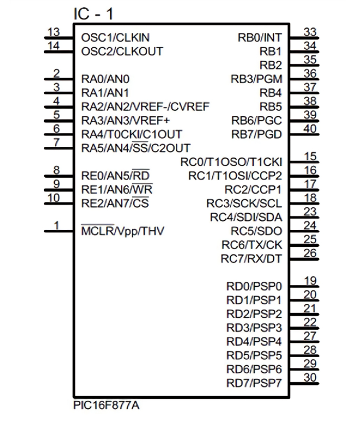
The PIC16F877A has 40 pins, with multiple functions assigned to each pin. Below is a summary of the pin configuration:
| Pin Number | Pin Name | Description |
|---|---|---|
| 1 | MCLR/VPP | Master Clear (Reset) input or programming voltage |
| 2-7 | RA0-RA5 | Analog inputs or general-purpose I/O |
| 8 | VSS | Ground |
| 9-10 | OSC1/OSC2 | Oscillator input/output |
| 11-18 | RB0-RB7 | General-purpose I/O or interrupt inputs |
| 19 | VDD | Positive supply voltage |
| 20-27 | RC0-RC7 | General-purpose I/O or peripheral functions |
| 28-33 | RD0-RD7 | General-purpose I/O |
| 34-40 | RE0-RE2 | Analog inputs or general-purpose I/O |
For a complete pinout and detailed descriptions, refer to the official datasheet.
Usage Instructions
How to Use the PIC16F877A in a Circuit
- Power Supply: Connect the VDD pin to a 5V power source and the VSS pin to ground.
- Oscillator Setup: Connect a crystal oscillator (e.g., 4 MHz) between OSC1 and OSC2 pins, along with two capacitors (22 pF) to stabilize the clock signal.
- Reset Circuit: Connect a pull-up resistor (10 kΩ) to the MCLR pin for proper reset functionality.
- I/O Configuration: Configure the I/O pins as input or output in the software using the TRISx registers.
- Programming: Use an ICSP (In-Circuit Serial Programming) tool to load your program into the microcontroller.
Important Considerations and Best Practices
- Decoupling Capacitors: Place a 0.1 µF capacitor close to the VDD and VSS pins to filter noise.
- Unused Pins: Configure unused pins as outputs or connect them to ground to avoid floating states.
- Clock Frequency: Ensure the clock frequency does not exceed the microcontroller's maximum rating (20 MHz).
- Programming Voltage: During programming, apply a voltage of 13V to the MCLR pin.
Example Code for Arduino UNO Integration
The PIC16F877A can communicate with an Arduino UNO via UART. Below is an example of how to send data from the Arduino to the PIC16F877A:
Arduino Code
void setup() {
  Serial.begin(9600); // Initialize UART communication at 9600 baud rate
}

void loop() {
  Serial.println("Hello, PIC16F877A!"); // Send data to the PIC
  delay(1000); // Wait for 1 second
}
PIC16F877A Code (Using MPLAB XC8 Compiler)
#include <xc.h>

// Configuration bits
#pragma config FOSC = XT        // Oscillator Selection (XT oscillator)
#pragma config WDTE = OFF       // Watchdog Timer Enable (WDT disabled)
#pragma config PWRTE = ON       // Power-up Timer Enable
#pragma config BOREN = ON       // Brown-out Reset Enable
#pragma config LVP = OFF        // Low-Voltage Programming Disable
#pragma config CPD = OFF        // Data EEPROM Memory Code Protection
#pragma config WRT = OFF        // Flash Program Memory Write Enable
#pragma config CP = OFF         // Flash Program Memory Code Protection

#define _XTAL_FREQ 4000000      // Define the clock frequency (4 MHz)

void UART_Init() {
    TRISC6 = 0; // TX pin as output
    TRISC7 = 1; // RX pin as input
    SPBRG = 25; // Baud rate = 9600 for 4 MHz clock
    TXEN = 1;   // Enable transmission
    SPEN = 1;   // Enable serial port
}

void UART_Write(char data) {
    while (!TXIF); // Wait until the transmit buffer is empty
    TXREG = data;  // Load the data into the transmit register
}

void main() {
    UART_Init(); // Initialize UART
    while (1) {
        UART_Write('H'); // Send 'H' to Arduino
        UART_Write('i'); // Send 'i' to Arduino
        __delay_ms(1000); // Wait for 1 second
    }
}
Troubleshooting and FAQs
Common Issues and Solutions
Microcontroller Not Responding
- Cause: Incorrect power supply or missing decoupling capacitors.
- Solution: Verify the power supply connections and add a 0.1 µF capacitor near the VDD and VSS pins.
Program Not Running
- Cause: Incorrect oscillator configuration.
- Solution: Ensure the crystal oscillator and capacitors are properly connected to OSC1 and OSC2.
UART Communication Fails
- Cause: Mismatched baud rates between devices.
- Solution: Verify that both the PIC16F877A and the external device (e.g., Arduino) are configured to use the same baud rate.
EEPROM Data Loss
- Cause: Power failure during write operations.
- Solution: Use a stable power supply and avoid writing to EEPROM during power fluctuations.
FAQs
Q: Can the PIC16F877A operate at 3.3V?
- A: Yes, the PIC16F877A can operate at voltages as low as 2.0V, but ensure the clock frequency is adjusted accordingly.
Q: How many times can the EEPROM be written?
- A: The EEPROM can be written up to 1,000,000 times as per the manufacturer's specifications.
Q: Can I use the PIC16F877A for PWM applications?
- A: Yes, the PIC16F877A has built-in PWM modules that can be used for motor control and other applications.
Q: Is the PIC16F877A compatible with modern IDEs?
- A: Yes, it is supported by Microchip's MPLAB X IDE and the XC8 compiler.
This concludes the documentation for the PIC16F877A microcontroller. For further details, refer to the official datasheet provided by Microchip Technology.