How to Use CT PZEM004T: Examples, Pinouts, and Specs

Introduction
The CT PZEM004T is a multifunctional energy meter designed to measure key electrical parameters such as voltage, current, power, energy, and frequency. It is specifically built to work with current transformers (CTs), making it ideal for monitoring AC electrical systems. This component is widely used in energy management systems, industrial automation, and home energy monitoring applications. Its ability to provide real-time data makes it a valuable tool for analyzing energy efficiency and optimizing power usage.
Explore Projects Built with CT PZEM004T


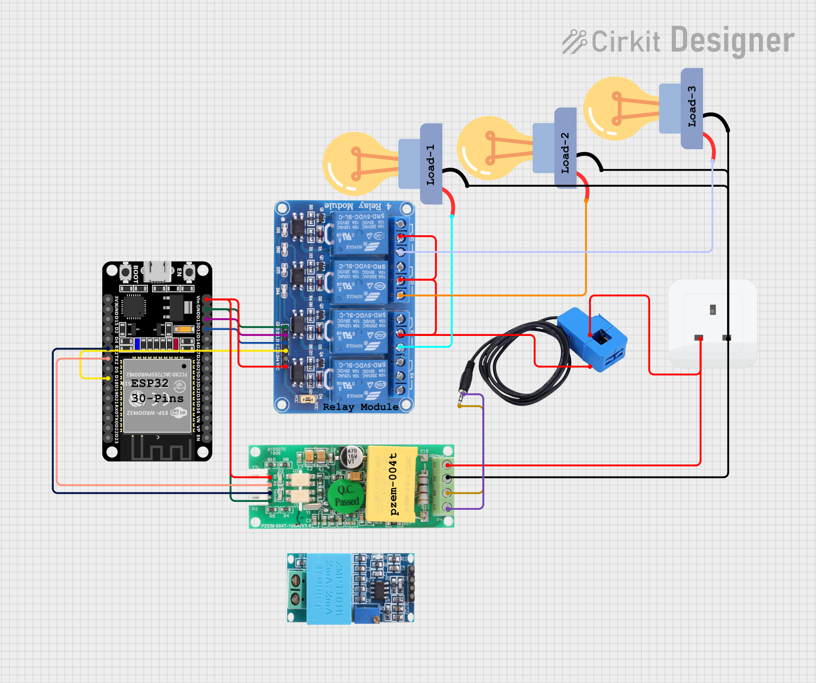
Explore Projects Built with CT PZEM004T
Common Applications
- Home energy monitoring systems
- Industrial power management
- Renewable energy systems (e.g., solar inverters)
- Smart grid applications
- Electrical load analysis and diagnostics
Technical Specifications
The CT PZEM004T is a compact and efficient energy meter with the following key specifications:
| Parameter | Specification |
|---|---|
| Voltage Range | 80V - 260V AC |
| Current Range | 0A - 100A (with external CT) |
| Power Range | 0W - 22kW |
| Energy Range | 0kWh - 9999kWh |
| Frequency Range | 45Hz - 65Hz |
| Communication Protocol | UART (9600 baud rate) |
| Power Supply | 5V DC (external power required) |
| Accuracy | ±0.5% (under standard conditions) |
| Dimensions | 48mm x 29mm x 21mm |
Pin Configuration
The CT PZEM004T module has a simple pinout for easy integration into circuits. Below is the pin configuration:
| Pin Name | Description |
|---|---|
| VCC | Power supply input (5V DC) |
| GND | Ground connection |
| TX | UART Transmit pin (connects to RX of MCU) |
| RX | UART Receive pin (connects to TX of MCU) |
Usage Instructions
Connecting the CT PZEM004T to an Arduino UNO
To use the CT PZEM004T with an Arduino UNO, follow these steps:
Wiring the Module:
- Connect the
VCCpin of the PZEM004T to the 5V pin of the Arduino UNO. - Connect the
GNDpin of the PZEM004T to the GND pin of the Arduino UNO. - Connect the
TXpin of the PZEM004T to theRXpin of the Arduino UNO. - Connect the
RXpin of the PZEM004T to theTXpin of the Arduino UNO. - Attach the current transformer (CT) to the PZEM004T and clamp it around the live wire of the AC circuit to be measured.
- Connect the
Install Required Libraries:
- Download and install the
PZEM004Tlibrary for Arduino from the Arduino Library Manager or GitHub.
- Download and install the
Upload the Code: Use the following example code to read data from the PZEM004T and display it on the Serial Monitor:
#include <PZEM004Tv30.h> // Include the PZEM004T library

// Create a PZEM004T object with RX and TX pins
PZEM004Tv30 pzem(2, 3); // RX = pin 2, TX = pin 3

void setup() {
    Serial.begin(9600); // Initialize Serial Monitor
    Serial.println("PZEM004T Energy Meter Example");
}

void loop() {
    // Read voltage
    float voltage = pzem.voltage();
    if (!isnan(voltage)) {
        Serial.print("Voltage: ");
        Serial.print(voltage);
        Serial.println(" V");
    } else {
        Serial.println("Error reading voltage");
    }

    // Read current
    float current = pzem.current();
    if (!isnan(current)) {
        Serial.print("Current: ");
        Serial.print(current);
        Serial.println(" A");
    } else {
        Serial.println("Error reading current");
    }

    // Read power
    float power = pzem.power();
    if (!isnan(power)) {
        Serial.print("Power: ");
        Serial.print(power);
        Serial.println(" W");
    } else {
        Serial.println("Error reading power");
    }

    // Read energy
    float energy = pzem.energy();
    if (!isnan(energy)) {
        Serial.print("Energy: ");
        Serial.print(energy);
        Serial.println(" kWh");
    } else {
        Serial.println("Error reading energy");
    }

    // Read frequency
    float frequency = pzem.frequency();
    if (!isnan(frequency)) {
        Serial.print("Frequency: ");
        Serial.print(frequency);
        Serial.println(" Hz");
    } else {
        Serial.println("Error reading frequency");
    }

    // Wait 1 second before the next reading
    delay(1000);
}
Important Considerations
- Ensure the current transformer (CT) is properly clamped around the live wire of the AC circuit. Incorrect placement may result in inaccurate readings.
- The PZEM004T requires an external 5V DC power supply for operation.
- Avoid exceeding the specified voltage and current ranges to prevent damage to the module.
- Use proper isolation techniques when working with high-voltage AC circuits to ensure safety.
Troubleshooting and FAQs
Common Issues and Solutions
No Data on Serial Monitor:
- Ensure the
TXandRXpins are correctly connected between the PZEM004T and the Arduino UNO. - Verify that the baud rate in the Serial Monitor is set to 9600.
- Ensure the
Inaccurate Readings:
- Check that the CT is securely clamped around the live wire and not the neutral wire.
- Ensure the load being measured is within the specified range of the PZEM004T.
Error Messages in Code:
- Ensure the PZEM004T library is correctly installed in the Arduino IDE.
- Verify that the correct pins are defined in the code for
RXandTX.
Module Not Powering On:
- Confirm that the
VCCpin is receiving a stable 5V DC supply. - Check all connections for loose wires or poor soldering.
- Confirm that the
FAQs
Q: Can the PZEM004T measure DC circuits?
A: No, the PZEM004T is designed specifically for AC circuits and cannot measure DC parameters.
Q: What is the maximum current the PZEM004T can measure?
A: The module can measure up to 100A when used with the appropriate current transformer (CT).
Q: Can I use multiple PZEM004T modules with a single Arduino?
A: Yes, multiple modules can be used by assigning unique addresses to each module and using a software serial library to manage communication.
Q: Is the PZEM004T safe to use with high-voltage systems?
A: Yes, but proper isolation and safety precautions must be followed when working with high-voltage AC circuits.