How to Use Rocker Switch: Examples, Pinouts, and Specs
Introduction
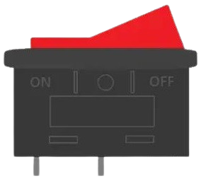
A rocker switch is a type of electrical switch that operates by rocking a lever back and forth to open or close a circuit. It is widely used in various applications due to its simplicity, durability, and ease of operation. Rocker switches are commonly employed to control power to devices, such as household appliances, power tools, and electronic equipment. They are available in various sizes, shapes, and configurations, making them versatile for different use cases.
Explore Projects Built with Rocker Switch

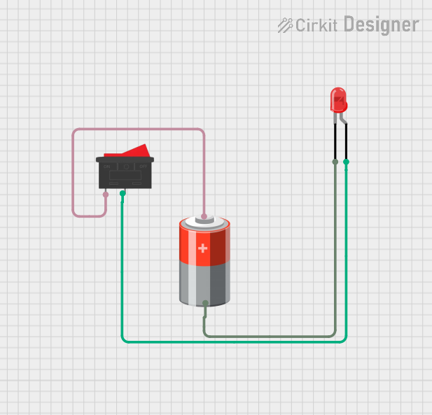
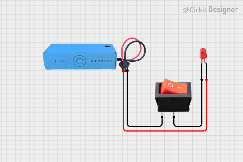
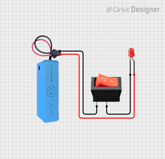
Explore Projects Built with Rocker Switch
Common Applications and Use Cases
- Power control for household appliances (e.g., lamps, fans, and coffee makers)
- On/off control for electronic devices and circuits
- Automotive applications (e.g., dashboard switches for lights or accessories)
- Industrial equipment and machinery
- DIY electronics projects
Technical Specifications
Below are the general technical specifications for a standard rocker switch. Note that specific values may vary depending on the model and manufacturer.
Key Technical Details
- Voltage Rating: Typically 12V, 24V, or 120V AC/DC (check specific model)
- Current Rating: Commonly 5A, 10A, or 15A
- Switch Type: SPST (Single Pole Single Throw) or DPDT (Double Pole Double Throw)
- Contact Resistance: ≤ 50 mΩ
- Insulation Resistance: ≥ 100 MΩ at 500V DC
- Operating Temperature: -25°C to 85°C
- Mechanical Life: 10,000 to 50,000 cycles (varies by model)
Pin Configuration and Descriptions
Rocker switches typically have 2, 3, or 6 pins, depending on their type and functionality. Below is a table describing the pin configuration for common types:
SPST Rocker Switch (2 Pins)
| Pin Number | Description |
|---|---|
| 1 | Input (Power Source) |
| 2 | Output (Load Connection) |
SPST Rocker Switch with LED Indicator (3 Pins)
| Pin Number | Description |
|---|---|
| 1 | Input (Power Source) |
| 2 | Output (Load Connection) |
| 3 | LED Ground (for Indicator Light) |
DPDT Rocker Switch (6 Pins)
| Pin Number | Description |
|---|---|
| 1, 4 | Input (Power Source) |
| 2, 5 | Output 1 (Load 1) |
| 3, 6 | Output 2 (Load 2) |
Usage Instructions
How to Use the Component in a Circuit
- Identify the Pins: Refer to the pin configuration table above to determine the input, output, and optional LED pins.
- Connect the Power Source: Attach the positive terminal of the power source to the input pin of the rocker switch.
- Connect the Load: Connect the output pin to the device or circuit you want to control.
- Optional LED Connection: If the rocker switch has an LED indicator, connect the LED ground pin to the negative terminal of the power source.
- Secure the Connections: Use soldering or crimp connectors to ensure reliable electrical connections.
- Test the Circuit: Toggle the rocker switch to verify that it properly controls the power to the load.
Important Considerations and Best Practices
- Voltage and Current Ratings: Ensure the switch's voltage and current ratings match or exceed the requirements of your circuit.
- Polarity: For switches with LED indicators, observe the correct polarity when connecting the LED ground pin.
- Mounting: Use the appropriate panel cutout size and mounting hardware to securely install the switch.
- Safety: Always disconnect the power source before wiring or modifying the circuit to avoid electric shock or damage.
Example: Connecting a Rocker Switch to an Arduino UNO
Below is an example of how to use a rocker switch to control an LED with an Arduino UNO:
// Example: Using a rocker switch to control an LED with Arduino UNO

const int rockerSwitchPin = 2; // Pin connected to the rocker switch
const int ledPin = 13;         // Pin connected to the LED

void setup() {
  pinMode(rockerSwitchPin, INPUT_PULLUP); // Set rocker switch pin as input with pull-up
  pinMode(ledPin, OUTPUT);               // Set LED pin as output
}

void loop() {
  int switchState = digitalRead(rockerSwitchPin); // Read the state of the rocker switch

  if (switchState == LOW) { // If the switch is ON (connected to ground)
    digitalWrite(ledPin, HIGH); // Turn on the LED
  } else {
    digitalWrite(ledPin, LOW);  // Turn off the LED
  }
}
Troubleshooting and FAQs
Common Issues and Solutions
Switch Not Working
- Cause: Loose or incorrect wiring.
- Solution: Double-check the connections and ensure the input and output pins are correctly wired.
LED Indicator Not Lighting Up
- Cause: Incorrect polarity or insufficient voltage.
- Solution: Verify the LED ground pin is connected to the negative terminal and check the voltage rating.
Switch Overheating
- Cause: Exceeding the current or voltage rating.
- Solution: Use a switch with a higher rating or reduce the load on the circuit.
Intermittent Operation
- Cause: Worn-out contacts or poor connections.
- Solution: Replace the switch or ensure all connections are secure.
FAQs
Q: Can I use a rocker switch to control AC devices?
A: Yes, as long as the switch's voltage and current ratings are suitable for the AC device.
Q: How do I know if my rocker switch has an LED indicator?
A: Look for an additional pin labeled as "LED" or "Ground" in the datasheet or on the switch itself.
Q: Can I use a rocker switch in a low-voltage DC circuit?
A: Yes, rocker switches are commonly used in low-voltage DC circuits, such as 12V or 24V systems.
Q: How do I mount a rocker switch on a panel?
A: Use the recommended panel cutout dimensions provided in the switch's datasheet and secure it with the built-in clips or screws.