How to Use MAX9814: Examples, Pinouts, and Specs
Introduction
The MAX9814 is a low-noise microphone amplifier with an integrated Automatic Gain Control (AGC) circuit, designed to deliver high-quality audio performance. Manufactured by Arduino, this component is optimized for applications requiring consistent audio levels and clear sound capture. The AGC feature automatically adjusts the gain based on the input signal level, ensuring a stable and distortion-free output.
Explore Projects Built with MAX9814


Explore Projects Built with MAX9814
Common Applications and Use Cases
- Voice recognition systems
- Portable audio devices
- Smart home assistants
- Audio recording equipment
- Communication devices
- Noise-canceling systems
Technical Specifications
The MAX9814 is designed to operate efficiently in a variety of audio applications. Below are its key technical specifications:
| Parameter | Value |
|---|---|
| Supply Voltage (Vcc) | 2.7V to 5.5V |
| Quiescent Current | 1.8mA (typical) |
| Input Type | Microphone (Electret or MEMS) |
| Output Type | Analog |
| Gain Control | Automatic Gain Control (AGC) |
| Maximum Gain | 40dB |
| Noise Floor | 8µV RMS (typical) |
| THD (Total Harmonic Distortion) | 0.04% (typical) |
| Operating Temperature Range | -40°C to +85°C |
Pin Configuration and Descriptions
The MAX9814 is typically available in an 8-pin package. Below is the pinout and description:
| Pin Number | Pin Name | Description |
|---|---|---|
| 1 | OUT | Analog audio output. Connect to the next stage of the audio circuit. |
| 2 | GND | Ground. Connect to the system ground. |
| 3 | VDD | Power supply input. Connect to a 2.7V to 5.5V power source. |
| 4 | BYPASS | Bypass capacitor connection for noise filtering. Connect a 0.1µF capacitor. |
| 5 | IN+ | Non-inverting microphone input. Connect to the positive terminal of the mic. |
| 6 | IN- | Inverting microphone input. Connect to the negative terminal of the mic. |
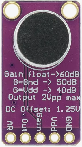
| 7 | GAIN | Gain control pin. Connect a resistor to set the gain or leave floating for AGC. |
| 8 | SHDN | Shutdown pin. Pull low to disable the amplifier and reduce power consumption. |
Usage Instructions
The MAX9814 is straightforward to use in audio circuits. Below are the steps and considerations for integrating it into your design:
Basic Circuit Connection
- Power Supply: Connect the VDD pin to a stable power source (2.7V to 5.5V). Add a decoupling capacitor (e.g., 0.1µF) close to the VDD pin to reduce noise.
- Microphone Input: Connect the microphone's positive terminal to the IN+ pin and the negative terminal to the IN- pin. Use a coupling capacitor (e.g., 1µF) if required by your microphone.
- Output: Connect the OUT pin to the next stage of your audio circuit, such as an ADC or speaker driver.
- Gain Control: To use the AGC feature, leave the GAIN pin floating. Alternatively, connect a resistor to set a fixed gain.
- Shutdown: If you need to disable the amplifier, pull the SHDN pin low. Leave it high or floating for normal operation.
- Bypass Capacitor: Connect a 0.1µF capacitor to the BYPASS pin for noise filtering.
Example Circuit with Arduino UNO
The MAX9814 can be easily interfaced with an Arduino UNO for audio signal processing. Below is an example:
Circuit Diagram
- Connect the MAX9814's OUT pin to the Arduino's analog input pin (e.g., A0).
- Connect the VDD pin to the Arduino's 5V pin.
- Connect the GND pin to the Arduino's GND.
Example Code
// MAX9814 Example Code for Arduino UNO
// This code reads the analog output from the MAX9814 and prints the values
// to the Serial Monitor for analysis.

const int micPin = A0; // Analog pin connected to MAX9814 OUT pin

void setup() {
  Serial.begin(9600); // Initialize serial communication at 9600 baud
  pinMode(micPin, INPUT); // Set the microphone pin as input
}

void loop() {
  int micValue = analogRead(micPin); // Read the analog value from the mic
  Serial.println(micValue); // Print the value to the Serial Monitor
  delay(10); // Small delay for stability
}
Important Considerations
- Power Supply Noise: Ensure the power supply is clean to avoid introducing noise into the audio signal.
- Microphone Type: The MAX9814 is compatible with both electret and MEMS microphones. Verify the microphone's specifications before use.
- AGC Settings: The AGC feature is ideal for dynamic audio environments. If a fixed gain is preferred, use an appropriate resistor on the GAIN pin.
- Bypass Capacitor: Always use a bypass capacitor on the BYPASS pin to minimize noise and improve stability.
Troubleshooting and FAQs
Common Issues and Solutions
No Output Signal
- Cause: Incorrect wiring or power supply issues.
- Solution: Verify all connections, especially the power supply and microphone input.
Distorted Audio
- Cause: Overloading the input or incorrect gain settings.
- Solution: Check the microphone's output level and adjust the gain settings accordingly.
High Noise Floor
- Cause: Insufficient bypass capacitor or noisy power supply.
- Solution: Ensure a 0.1µF capacitor is connected to the BYPASS pin and use a clean power source.
AGC Not Working
- Cause: GAIN pin improperly configured.
- Solution: Leave the GAIN pin floating for AGC operation or verify the resistor value for fixed gain.
FAQs
Can the MAX9814 work with a 3.3V system?
- Yes, the MAX9814 operates with supply voltages as low as 2.7V, making it compatible with 3.3V systems.
What type of microphone is recommended?
- Both electret and MEMS microphones are supported. Ensure the microphone's output impedance matches the MAX9814's input requirements.
How do I disable the amplifier?
- Pull the SHDN pin low to disable the amplifier and reduce power consumption.
Can I use the MAX9814 for stereo audio?
- No, the MAX9814 is a single-channel amplifier. For stereo applications, use two MAX9814 modules.
By following this documentation, you can effectively integrate the MAX9814 into your audio projects for high-quality sound capture and processing.