Cirkit Designer Logo
Cirkit Designer
Your all-in-one circuit design IDE
Home / 
Component Documentation

How to Use huskylense: Examples, Pinouts, and Specs

Image of huskylense
Cirkit Designer LogoDesign with huskylense in Cirkit Designer

Introduction

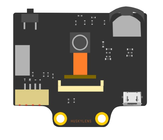
The HuskyLens is an easy-to-use AI camera module that provides powerful machine learning capabilities to any project. It is designed to interface with microcontrollers such as the Arduino UNO, enabling applications in robotics, automation, and interactive art. With its ability to perform tasks such as facial recognition, object tracking, and color detection, the HuskyLens is a versatile component for hobbyists and professionals alike.

Explore Projects Built with huskylense

Use Cirkit Designer to design, explore, and prototype these projects online. Some projects support real-time simulation. Click "Open Project" to start designing instantly!
Arduino Uno R3 Controlled Pan-Tilt Security Camera with Night Vision
Image of MOTION CAMERA: A project utilizing huskylense in a practical application
This circuit features an Arduino Uno R3 microcontroller connected to a Huskylens (an AI camera module), an IR LED Night Vision Ring, and a Tilt Pan module. The Huskylens is interfaced with the Arduino via I2C communication using the SDA and SCL lines, while the Tilt Pan module is controlled by the Arduino through digital pins 10 and 11 for signal and output control. The IR LED ring and Tilt Pan are powered directly from the Arduino's 5V output, and all components share a common ground.
Cirkit Designer LogoOpen Project in Cirkit Designer
Arduino UNO Controlled RGB LED and Servo System with Capacitive Sensing and HuskyLens Vision
Image of orca: A project utilizing huskylense in a practical application
This circuit features an Arduino UNO microcontroller connected to a Huskylens for image processing, a capacitive sensor for touch input, and a multi-channel PWM servo shield controlling several servos. The Arduino is powered by 5V and shares a common ground with the Huskylens and capacitive sensor, which also interface with the Arduino's analog and I2C pins, respectively. The servos are powered by a battery through a DC-DC step-down converter, and their control signals are managed by the PWM servo shield, which is also connected to the Arduino for I2C communication.
Cirkit Designer LogoOpen Project in Cirkit Designer
Raspberry Pi 5 Motion-Activated Dual DC Motor System with PIR Sensors
Image of Bhuvan: A project utilizing huskylense in a practical application
This circuit uses a Raspberry Pi 5 to control two DC motors via an L298N motor driver, based on input from two PIR motion sensors. The Raspberry Pi also interfaces with a Huskylens for additional sensor input and a 7-inch WaveShare display for output. Power is supplied by a 12V battery for the motor driver and a 5V battery for the display.
Cirkit Designer LogoOpen Project in Cirkit Designer
ESP8266 Smart Dustbin with Ultrasonic and IR Sensors
Image of Smart Dustbin: A project utilizing huskylense in a practical application
This circuit is a smart dustbin system that uses an ESP8266 microcontroller to control an ultrasonic sensor for measuring the dustbin level, an IR sensor for obstacle detection, and a servo motor to open and close the dustbin lid. The system is powered via a USB power source and operates by opening the lid when an obstacle is detected and measuring the distance to determine the fill level of the dustbin.
Cirkit Designer LogoOpen Project in Cirkit Designer

Explore Projects Built with huskylense

Use Cirkit Designer to design, explore, and prototype these projects online. Some projects support real-time simulation. Click "Open Project" to start designing instantly!
Image of MOTION CAMERA: A project utilizing huskylense in a practical application
Arduino Uno R3 Controlled Pan-Tilt Security Camera with Night Vision
This circuit features an Arduino Uno R3 microcontroller connected to a Huskylens (an AI camera module), an IR LED Night Vision Ring, and a Tilt Pan module. The Huskylens is interfaced with the Arduino via I2C communication using the SDA and SCL lines, while the Tilt Pan module is controlled by the Arduino through digital pins 10 and 11 for signal and output control. The IR LED ring and Tilt Pan are powered directly from the Arduino's 5V output, and all components share a common ground.
Cirkit Designer LogoOpen Project in Cirkit Designer
Image of orca: A project utilizing huskylense in a practical application
Arduino UNO Controlled RGB LED and Servo System with Capacitive Sensing and HuskyLens Vision
This circuit features an Arduino UNO microcontroller connected to a Huskylens for image processing, a capacitive sensor for touch input, and a multi-channel PWM servo shield controlling several servos. The Arduino is powered by 5V and shares a common ground with the Huskylens and capacitive sensor, which also interface with the Arduino's analog and I2C pins, respectively. The servos are powered by a battery through a DC-DC step-down converter, and their control signals are managed by the PWM servo shield, which is also connected to the Arduino for I2C communication.
Cirkit Designer LogoOpen Project in Cirkit Designer
Image of Bhuvan: A project utilizing huskylense in a practical application
Raspberry Pi 5 Motion-Activated Dual DC Motor System with PIR Sensors
This circuit uses a Raspberry Pi 5 to control two DC motors via an L298N motor driver, based on input from two PIR motion sensors. The Raspberry Pi also interfaces with a Huskylens for additional sensor input and a 7-inch WaveShare display for output. Power is supplied by a 12V battery for the motor driver and a 5V battery for the display.
Cirkit Designer LogoOpen Project in Cirkit Designer
Image of Smart Dustbin: A project utilizing huskylense in a practical application
ESP8266 Smart Dustbin with Ultrasonic and IR Sensors
This circuit is a smart dustbin system that uses an ESP8266 microcontroller to control an ultrasonic sensor for measuring the dustbin level, an IR sensor for obstacle detection, and a servo motor to open and close the dustbin lid. The system is powered via a USB power source and operates by opening the lid when an obstacle is detected and measuring the distance to determine the fill level of the dustbin.
Cirkit Designer LogoOpen Project in Cirkit Designer

Common Applications and Use Cases

  • Robotics: Object tracking and avoidance, gesture control
  • Interactive installations: Audience engagement through gesture and face recognition
  • Educational projects: Introducing AI and machine learning concepts
  • DIY electronics: Adding vision capabilities to custom builds

Technical Specifications

Key Technical Details

  • Processor: Kendryte K210
  • Input Voltage: 3.3V to 5V
  • Interface: I2C, UART
  • Lens: Wide-angle lens
  • Resolution: 320x240 to 224x224
  • Frame Rate: Up to 30 frames per second

Pin Configuration and Descriptions

Pin Number Name Description
1 VCC Power supply (3.3V to 5V)
2 GND Ground connection
3 TX UART transmit
4 RX UART receive
5 SCL I2C clock
6 SDA I2C data

Usage Instructions

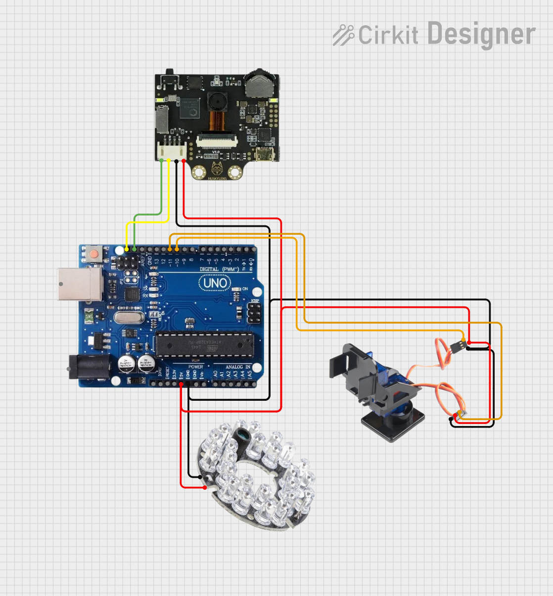
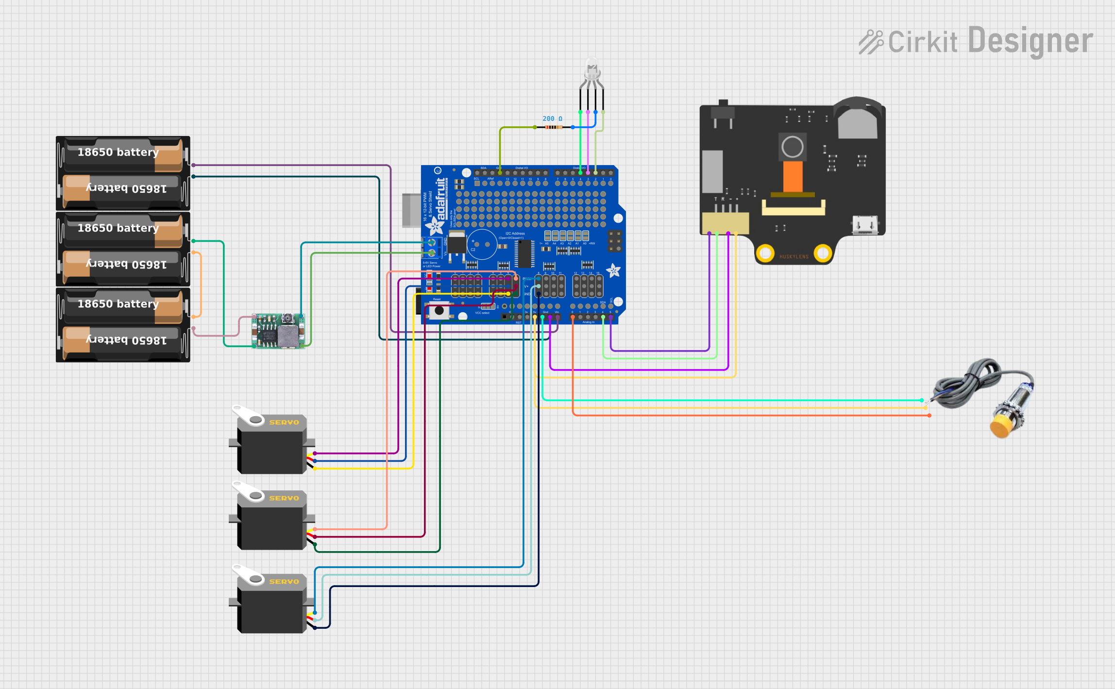
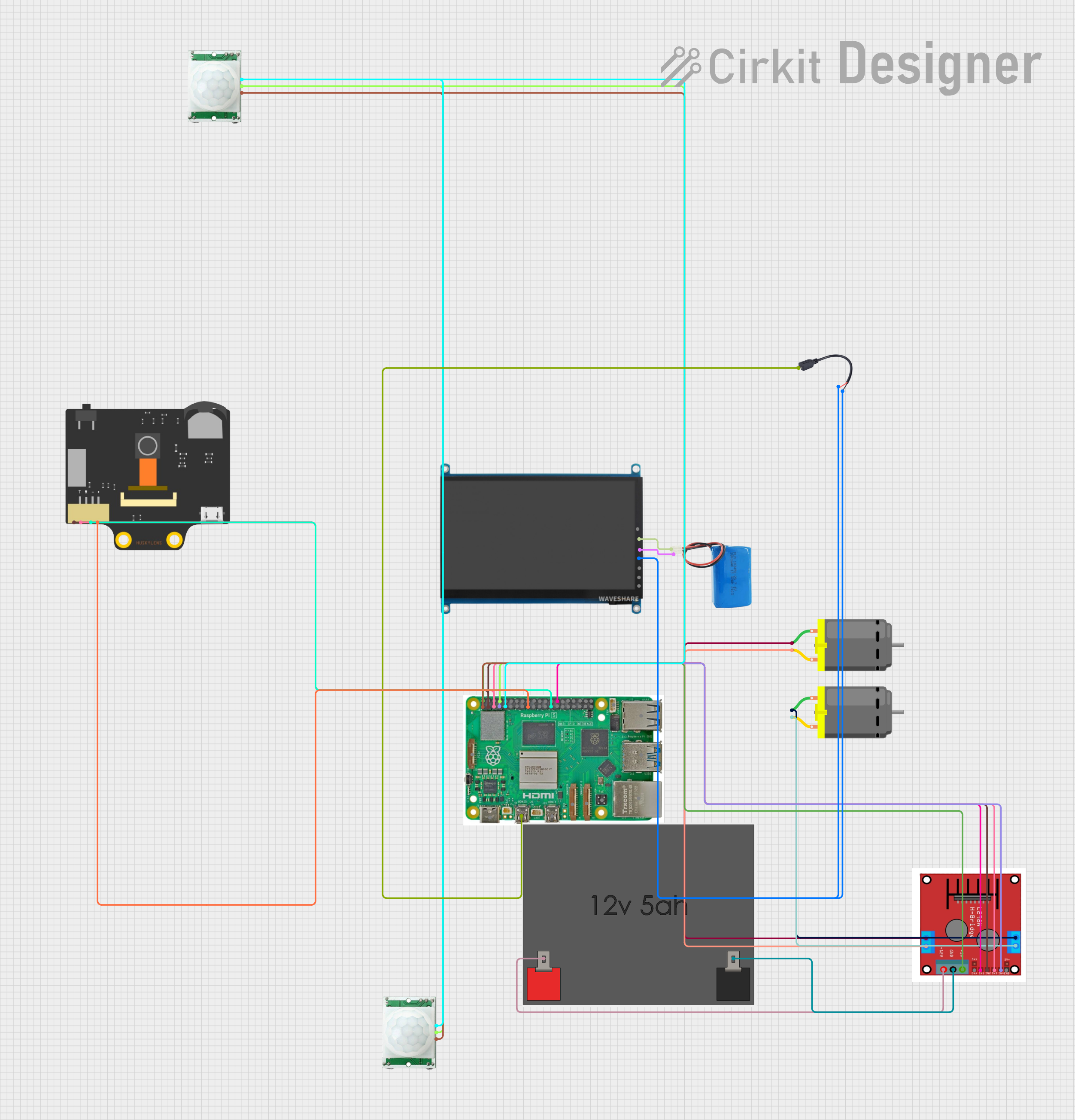
How to Use the HuskyLens in a Circuit

  1. Powering the HuskyLens: Connect the VCC pin to a 3.3V or 5V power supply and the GND pin to the ground.
  2. Data Communication: Choose between UART or I2C for communication.
    • For UART, connect the TX and RX pins to the corresponding RX and TX pins on the microcontroller.
    • For I2C, connect the SCL and SDA pins to the microcontroller's I2C pins.
  3. Lens Adjustment: Before powering on, adjust the focus of the lens by rotating it to ensure clear image capture.

Important Considerations and Best Practices

  • Ensure the power supply is within the specified voltage range to prevent damage.
  • Use pull-up resistors on the I2C lines if they are not built into the microcontroller.
  • When using UART, ensure that the baud rates of HuskyLens and the microcontroller match.
  • Regularly update the firmware of HuskyLens for optimal performance.

Troubleshooting and FAQs

Common Issues Users Might Face

  • Blurry Images: Adjust the focus of the lens until the image is clear.
  • Communication Errors: Verify the wiring, ensure correct baud rate for UART, and check for proper I2C pull-up resistors.
  • Power Issues: Confirm that the power supply is within the acceptable range and that connections are secure.

Solutions and Tips for Troubleshooting

  • If the HuskyLens is not recognized by the microcontroller, double-check the connection and the code for initializing the camera.
  • For unclear images, clean the lens with a soft, dry cloth to remove any fingerprints or dust.
  • In case of persistent issues, consult the HuskyLens forums and community for support.

Example Code for Arduino UNO

#include <SoftwareSerial.h>
#include "HUSKYLENS.h"

SoftwareSerial huskyLensSerial(2, 3); // RX, TX
HUSKYLENS huskyLens;

void setup() {
  huskyLensSerial.begin(9600);
  huskyLens.begin(huskyLensSerial);
  Serial.begin(9600);
}

void loop() {
  if (!huskyLens.request()) {
    Serial.println("Failed to request data from HUSKYLENS, check the connection!");
  } else {
    while (huskyLens.available()) {
      // Print result if object is recognized
      HUSKYLENSResult result = huskyLens.read();
      if (result.command == COMMAND_RETURN_BLOCK) {
        Serial.print("ID: ");
        Serial.print(result.id);
        Serial.print(" X Center: ");
        Serial.print(result.xCenter);
        Serial.print(" Y Center: ");
        Serial.println(result.yCenter);
      }
    }
  }
}

Note: This example assumes the use of the SoftwareSerial library to communicate with the HuskyLens. Adjust the pin numbers in the SoftwareSerial huskyLensSerial(2, 3); line to match your setup.

Remember to keep code comments concise and within the 80 character line length limit. Wrap comments as needed for clarity and readability.