How to Use Flowmeter Sensor: Examples, Pinouts, and Specs
Introduction
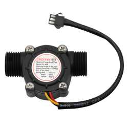
The Flowmeter Sensor (FMS), manufactured by Me, is a device designed to measure the flow rate of liquids or gases in a system. It provides accurate and reliable data, making it an essential component for monitoring and control in various applications. The sensor operates by detecting the flow of a medium and converting it into an electrical signal that can be processed by microcontrollers or other monitoring systems.
Explore Projects Built with Flowmeter Sensor
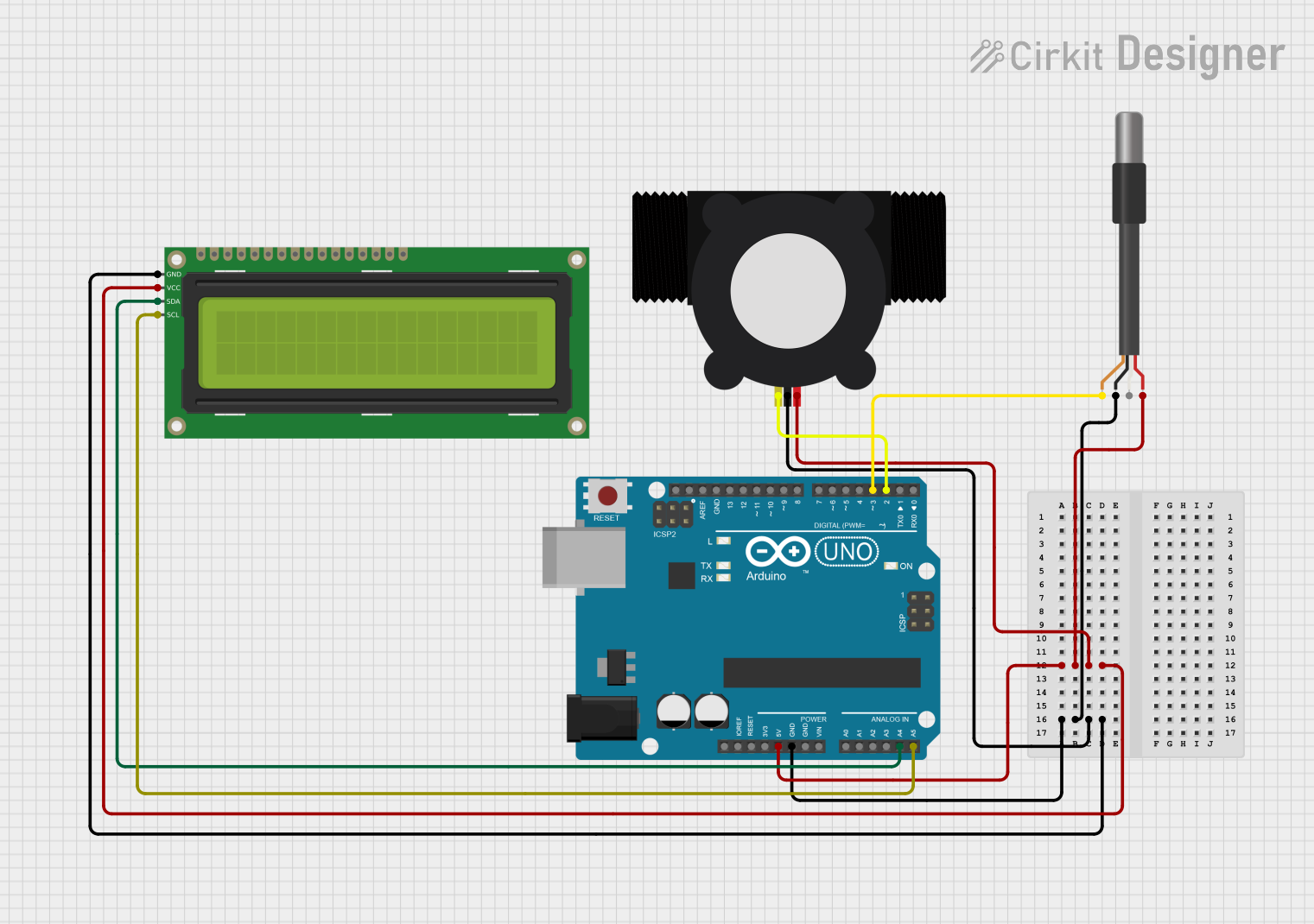
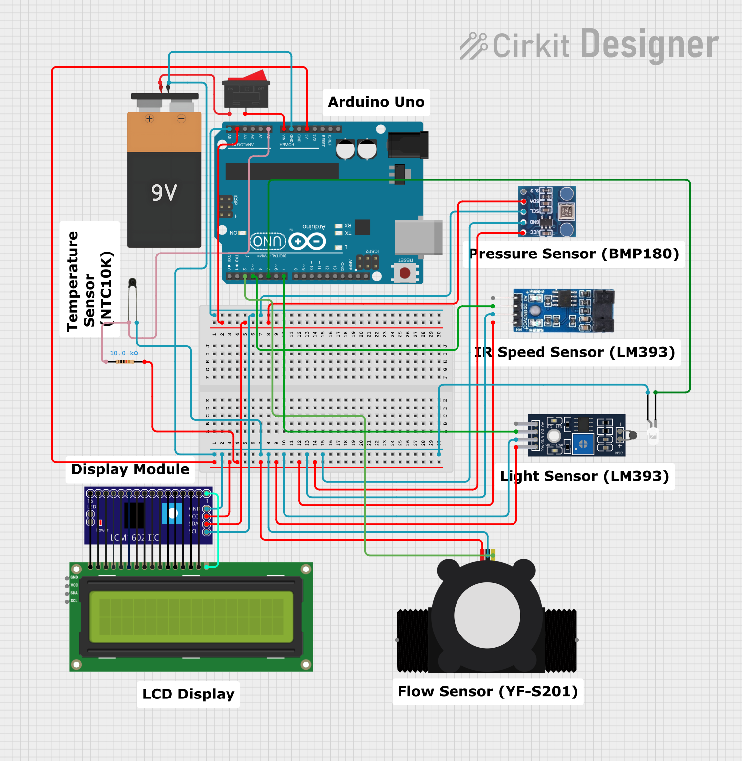
Explore Projects Built with Flowmeter Sensor
Common Applications and Use Cases
- Industrial process control and automation
- Water and gas flow monitoring in pipelines
- HVAC (Heating, Ventilation, and Air Conditioning) systems
- Agricultural irrigation systems
- Medical devices requiring precise fluid flow measurement
Technical Specifications
Below are the key technical details of the Flowmeter Sensor (FMS):
| Parameter | Value |
|---|---|
| Operating Voltage | 5V to 24V DC |
| Output Signal | Pulse signal (frequency-based) |
| Flow Rate Range | 1 L/min to 30 L/min |
| Accuracy | ±2% |
| Maximum Pressure | 1.75 MPa |
| Operating Temperature | -20°C to 85°C |
| Connector Type | 3-pin JST |
Pin Configuration and Descriptions
The Flowmeter Sensor has a 3-pin connector. The pinout is as follows:
| Pin | Name | Description |
|---|---|---|
| 1 | VCC | Power supply input (5V to 24V DC) |
| 2 | GND | Ground connection |
| 3 | Signal | Pulse output signal proportional to flow rate |
Usage Instructions
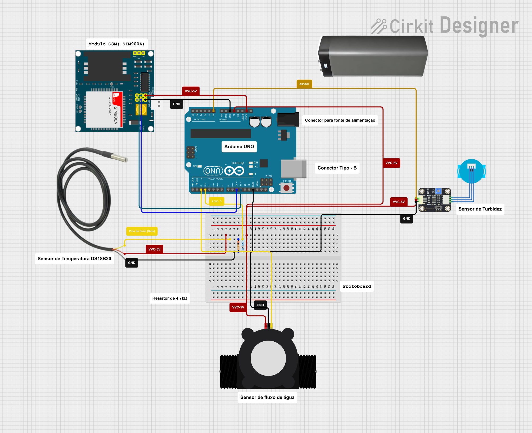
How to Use the Flowmeter Sensor in a Circuit
- Power the Sensor: Connect the VCC pin to a 5V to 24V DC power source and the GND pin to the ground of your circuit.
- Connect the Signal Pin: Attach the Signal pin to a digital input pin of a microcontroller (e.g., Arduino UNO). Use a pull-up resistor if necessary.
- Read the Output: The sensor outputs a pulse signal where the frequency is proportional to the flow rate. Count the pulses over a specific time interval to calculate the flow rate.
Important Considerations and Best Practices
- Ensure the sensor is installed in the correct orientation as indicated by the flow direction arrow on the body.
- Avoid exposing the sensor to pressures or temperatures beyond its rated limits.
- Use a filter to prevent debris from entering the sensor and affecting its accuracy.
- Calibrate the sensor in your specific system to account for variations in flow conditions.
Example Code for Arduino UNO
Below is an example code snippet to interface the Flowmeter Sensor with an Arduino UNO:
// Flowmeter Sensor Example Code
// Manufacturer: Me
// Part ID: FMS
// This code reads the pulse signal from the flowmeter sensor and calculates
// the flow rate in liters per minute (L/min).

const int flowPin = 2; // Signal pin connected to digital pin 2
volatile int pulseCount = 0; // Variable to store pulse count

// Flowmeter calibration factor (pulses per liter)
const float calibrationFactor = 4.5;

unsigned long previousMillis = 0;
const unsigned long interval = 1000; // 1 second interval for flow rate calculation

void setup() {
  pinMode(flowPin, INPUT_PULLUP); // Set flowPin as input with pull-up resistor
  attachInterrupt(digitalPinToInterrupt(flowPin), countPulse, RISING);
  Serial.begin(9600); // Initialize serial communication
}

void loop() {
  unsigned long currentMillis = millis();

  // Calculate flow rate every second
  if (currentMillis - previousMillis >= interval) {
    previousMillis = currentMillis;

    // Calculate flow rate in L/min
    float flowRate = (pulseCount / calibrationFactor);
    pulseCount = 0; // Reset pulse count for the next interval

    // Print flow rate to the serial monitor
    Serial.print("Flow Rate: ");
    Serial.print(flowRate);
    Serial.println(" L/min");
  }
}

// Interrupt service routine to count pulses
void countPulse() {
  pulseCount++;
}
Troubleshooting and FAQs
Common Issues and Solutions
No Output Signal
- Cause: Incorrect wiring or insufficient power supply.
- Solution: Verify the connections and ensure the power supply voltage is within the specified range (5V to 24V DC).
Inaccurate Flow Rate Readings
- Cause: Debris in the sensor or incorrect calibration.
- Solution: Clean the sensor and recalibrate it for your specific system.
Intermittent Signal
- Cause: Electrical noise or loose connections.
- Solution: Use shielded cables and ensure all connections are secure.
FAQs
Q: Can the Flowmeter Sensor measure gas flow?
A: Yes, the sensor can measure both liquid and gas flow, but ensure the medium is compatible with the sensor's materials and specifications.
Q: How do I calibrate the sensor?
A: Run a known volume of liquid through the sensor and count the pulses. Use this data to calculate the calibration factor (pulses per liter).
Q: Is the sensor waterproof?
A: The sensor is designed for inline use and can handle liquids, but it should not be submerged entirely in water.
Q: Can I use the sensor with a 3.3V microcontroller?
A: Yes, but ensure the signal output is compatible with the microcontroller's input voltage levels. Use a level shifter if necessary.