How to Use BH1750 BH1750FVI Chip Light: Examples, Pinouts, and Specs
Introduction
The BH1750 is a digital light sensor designed to measure ambient light levels in lux, providing precise and reliable readings. It communicates via the I2C protocol, making it easy to integrate into microcontroller-based systems. The sensor is highly sensitive and can detect a wide range of light intensities, from very dim to bright sunlight.
Explore Projects Built with BH1750 BH1750FVI Chip Light
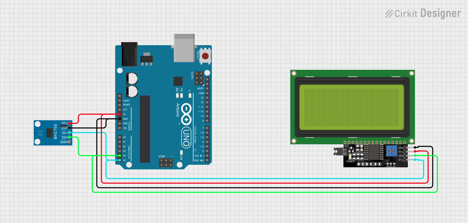
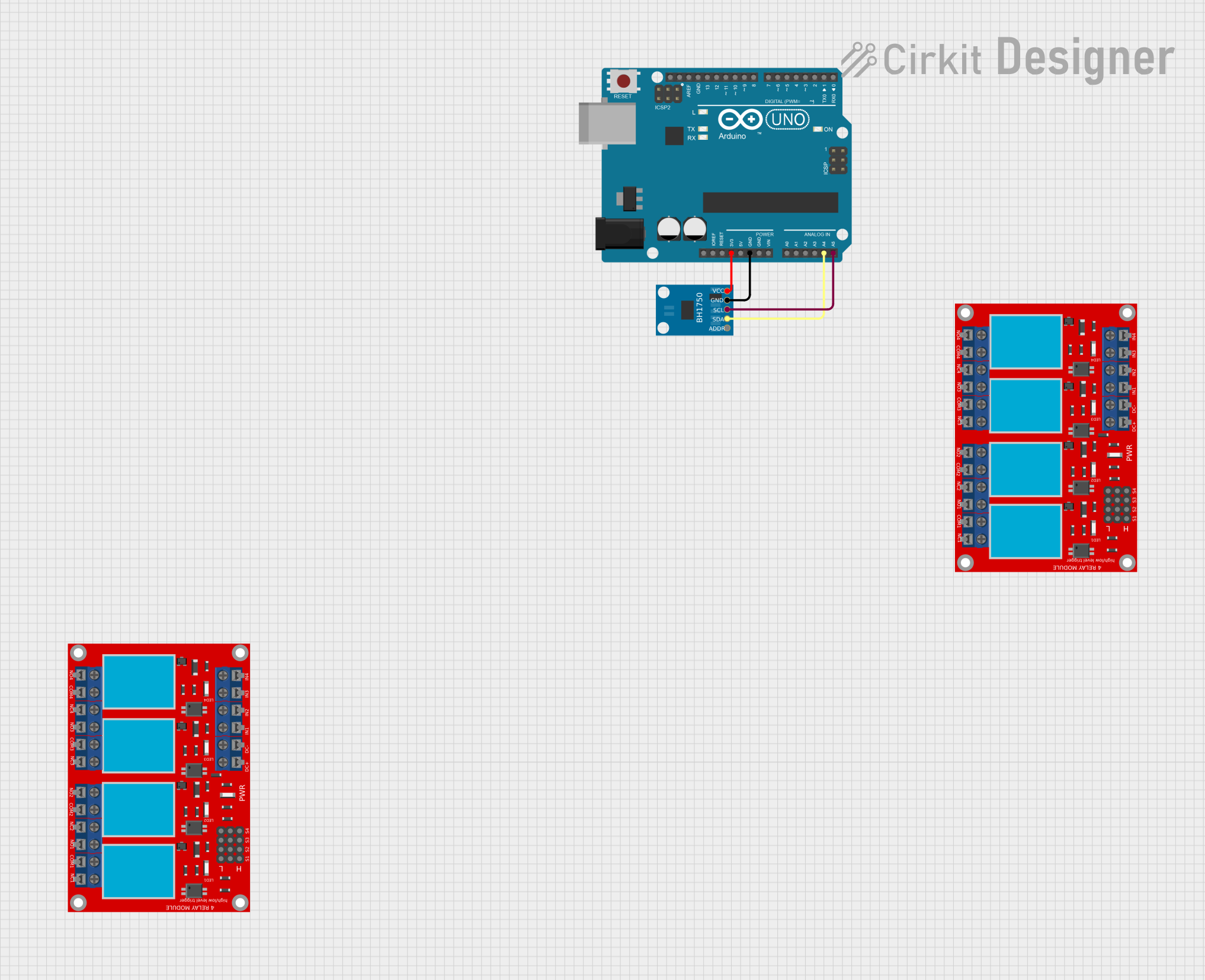
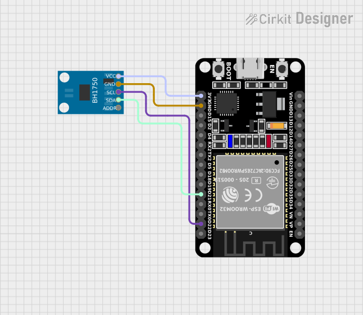
Explore Projects Built with BH1750 BH1750FVI Chip Light
Common Applications and Use Cases
- Automatic brightness control for LCD and OLED displays
- Energy-efficient lighting systems
- Smart home automation (e.g., light-based triggers)
- Weather monitoring stations
- Photography and camera exposure control
Technical Specifications
The BH1750 is a compact and efficient light sensor with the following key specifications:
| Parameter | Value |
|---|---|
| Operating Voltage | 2.4V to 3.6V |
| Operating Current | 0.12 mA (typical) |
| Measurement Range | 1 lux to 65535 lux |
| Communication Interface | I2C (7-bit address: 0x23 or 0x5C) |
| Resolution | 1 lux |
| Operating Temperature | -40°C to +85°C |
| Dimensions | 3.0mm x 1.6mm x 0.7mm |
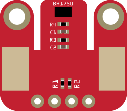
Pin Configuration and Descriptions
The BH1750 has six pins, as described in the table below:
| Pin Name | Pin Number | Description |
|---|---|---|
| VCC | 1 | Power supply (2.4V to 3.6V) |
| GND | 2 | Ground |
| SDA | 3 | I2C data line |
| SCL | 4 | I2C clock line |
| ADDR | 5 | I2C address selection (LOW: 0x23, HIGH: 0x5C) |
| NC | 6 | Not connected (leave floating or grounded) |
Usage Instructions
How to Use the BH1750 in a Circuit
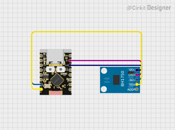
- Power the Sensor: Connect the VCC pin to a 3.3V power source and the GND pin to ground.
- I2C Communication: Connect the SDA and SCL pins to the corresponding I2C pins on your microcontroller. Use pull-up resistors (typically 4.7kΩ) on both lines if not already present on your board.
- Address Selection: Use the ADDR pin to select the I2C address:
- Connect to GND for address
0x23. - Connect to VCC for address
0x5C.
- Connect to GND for address
- Initialize the Sensor: Configure the I2C interface on your microcontroller and initialize the BH1750 in the desired mode (e.g., continuous high-resolution mode).
Important Considerations and Best Practices
- Avoid Direct Sunlight: While the BH1750 can measure high light levels, prolonged exposure to direct sunlight may affect its accuracy.
- Use Proper Decoupling: Place a 0.1µF ceramic capacitor close to the VCC and GND pins to stabilize the power supply.
- I2C Pull-Up Resistors: Ensure proper pull-up resistors are used on the SDA and SCL lines for reliable communication.
- Measurement Modes: The BH1750 supports multiple modes (e.g., high-resolution, low-resolution). Choose the mode that best suits your application to balance accuracy and power consumption.
Example Code for Arduino UNO
Below is an example of how to use the BH1750 with an Arduino UNO:
#include <Wire.h>
#include <BH1750.h>

// Create an instance of the BH1750 sensor
BH1750 lightMeter;

void setup() {
  Serial.begin(9600); // Initialize serial communication
  Wire.begin();       // Initialize I2C communication

  // Initialize the BH1750 sensor in continuous high-resolution mode
  if (lightMeter.begin(BH1750::CONTINUOUS_HIGH_RES_MODE)) {
    Serial.println("BH1750 initialized successfully.");
  } else {
    Serial.println("Error initializing BH1750. Check connections.");
    while (1); // Halt execution if initialization fails
  }
}

void loop() {
  // Read light level in lux
  float lux = lightMeter.readLightLevel();

  // Print the light level to the serial monitor
  if (lux >= 0) {
    Serial.print("Light Level: ");
    Serial.print(lux);
    Serial.println(" lux");
  } else {
    Serial.println("Error reading light level.");
  }

  delay(1000); // Wait 1 second before the next reading
}
Troubleshooting and FAQs
Common Issues and Solutions
No Response from the Sensor
- Cause: Incorrect I2C address or wiring.
- Solution: Verify the ADDR pin connection and ensure the correct I2C address is used in the code.
Inconsistent Readings
- Cause: Electrical noise or unstable power supply.
- Solution: Add a decoupling capacitor (0.1µF) near the sensor's VCC and GND pins.
Sensor Not Detected
- Cause: Missing pull-up resistors on SDA and SCL lines.
- Solution: Add 4.7kΩ pull-up resistors to the SDA and SCL lines.
Readings Stuck at Zero
- Cause: Sensor not initialized properly.
- Solution: Ensure the
begin()function is called in the setup and check for initialization errors.
FAQs
Q: Can the BH1750 measure light through glass or plastic?
A: Yes, the BH1750 can measure light through transparent materials, but the material may slightly attenuate the light intensity.
Q: What is the maximum distance for I2C communication with the BH1750?
A: The maximum distance depends on the pull-up resistor values and the I2C clock speed. For reliable communication, keep the distance under 1 meter.
Q: Can the BH1750 operate at 5V?
A: No, the BH1750 operates at a maximum voltage of 3.6V. Use a level shifter if interfacing with a 5V system.
Q: How do I switch between measurement modes?
A: Use the appropriate command in your code to set the desired mode. Refer to the BH1750 datasheet for mode-specific commands.