Cirkit Designer Logo
Cirkit Designer
Your all-in-one circuit design IDE
Home / 
Component Documentation

How to Use HC-SR505 Mini PIR Motion Sensing Module: Examples, Pinouts, and Specs

Image of HC-SR505 Mini PIR Motion Sensing Module
Cirkit Designer LogoDesign with HC-SR505 Mini PIR Motion Sensing Module in Cirkit Designer

Introduction

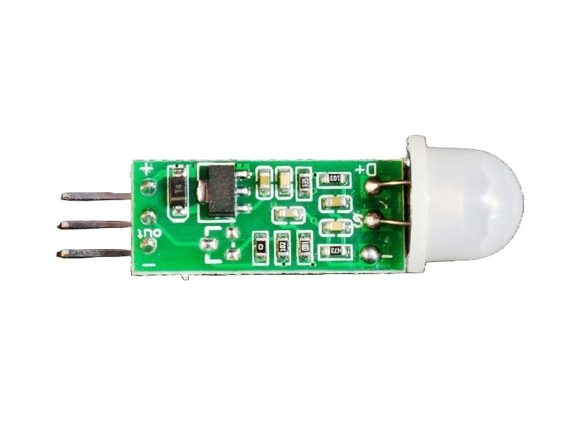
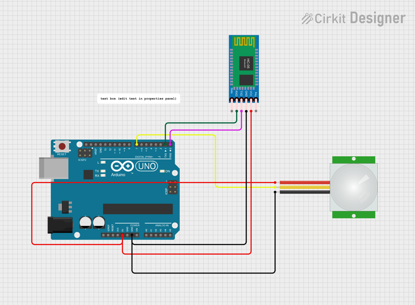
The HC-SR505 Mini PIR (Passive Infrared) Motion Sensing Module is a compact, low-power sensor capable of detecting the presence of humans or animals by sensing the infrared radiation they emit. This module is widely used in various applications such as security systems, automatic lighting, and home automation projects due to its small form factor and ease of use.

Explore Projects Built with HC-SR505 Mini PIR Motion Sensing Module

Use Cirkit Designer to design, explore, and prototype these projects online. Some projects support real-time simulation. Click "Open Project" to start designing instantly!
PIR Motion-Activated LED Light
Image of 0: A project utilizing HC-SR505 Mini PIR Motion Sensing Module in a practical application
This circuit is a simple motion-activated LED light system. The HC-SR505 Mini PIR Motion Sensing Module is powered by a 9V battery and detects motion, upon which it sends an output signal to turn on the red LED. The LED and the PIR sensor share a common ground with the battery, completing the circuit.
Cirkit Designer LogoOpen Project in Cirkit Designer
Arduino UNO-Based Security System with PIR Motion Detection and Bluetooth Connectivity
Image of 아두이노 캡스톤 : A project utilizing HC-SR505 Mini PIR Motion Sensing Module in a practical application
This circuit features an Arduino UNO microcontroller interfaced with a PIR motion sensor (HC-SR501), a Bluetooth module (HC-06), a buzzer (FIT0449), and a soil moisture sensor (SEN040129). The Arduino is programmed to interact with these sensors and actuators, likely to monitor environmental conditions and provide alerts or communication via Bluetooth. Additionally, there are two LED components (JLED-START and JLED-ARROW-9) daisy-chained together, which could be used for visual signaling or status indication.
Cirkit Designer LogoOpen Project in Cirkit Designer
ESP32 CAM-Based Wi-Fi Motion-Activated Smart Light
Image of ESP32 CAM: A project utilizing HC-SR505 Mini PIR Motion Sensing Module in a practical application
This circuit features an ESP32 CAM microcontroller connected to an HC-SR501 PIR motion sensor and a 2-channel relay module. The PIR sensor output is connected to a GPIO pin on the ESP32, allowing it to detect motion and signal the microcontroller. The ESP32 controls the relay, which in turn switches an AC bulb on or off, effectively creating a motion-activated light system.
Cirkit Designer LogoOpen Project in Cirkit Designer
Arduino UNO with PIR Sensor and Bluetooth Connectivity
Image of smart home security system: A project utilizing HC-SR505 Mini PIR Motion Sensing Module in a practical application
This circuit features an Arduino UNO connected to a PIR (Passive Infrared) sensor and an HC-05 Bluetooth module. The PIR sensor detects motion and sends a signal to the Arduino, which then communicates via Bluetooth using the HC-05 module. The embedded code on the Arduino is configured to send a specific message over serial when motion is detected by the PIR sensor.
Cirkit Designer LogoOpen Project in Cirkit Designer

Explore Projects Built with HC-SR505 Mini PIR Motion Sensing Module

Use Cirkit Designer to design, explore, and prototype these projects online. Some projects support real-time simulation. Click "Open Project" to start designing instantly!
Image of 0: A project utilizing HC-SR505 Mini PIR Motion Sensing Module in a practical application
PIR Motion-Activated LED Light
This circuit is a simple motion-activated LED light system. The HC-SR505 Mini PIR Motion Sensing Module is powered by a 9V battery and detects motion, upon which it sends an output signal to turn on the red LED. The LED and the PIR sensor share a common ground with the battery, completing the circuit.
Cirkit Designer LogoOpen Project in Cirkit Designer
Image of 아두이노 캡스톤 : A project utilizing HC-SR505 Mini PIR Motion Sensing Module in a practical application
Arduino UNO-Based Security System with PIR Motion Detection and Bluetooth Connectivity
This circuit features an Arduino UNO microcontroller interfaced with a PIR motion sensor (HC-SR501), a Bluetooth module (HC-06), a buzzer (FIT0449), and a soil moisture sensor (SEN040129). The Arduino is programmed to interact with these sensors and actuators, likely to monitor environmental conditions and provide alerts or communication via Bluetooth. Additionally, there are two LED components (JLED-START and JLED-ARROW-9) daisy-chained together, which could be used for visual signaling or status indication.
Cirkit Designer LogoOpen Project in Cirkit Designer
Image of ESP32 CAM: A project utilizing HC-SR505 Mini PIR Motion Sensing Module in a practical application
ESP32 CAM-Based Wi-Fi Motion-Activated Smart Light
This circuit features an ESP32 CAM microcontroller connected to an HC-SR501 PIR motion sensor and a 2-channel relay module. The PIR sensor output is connected to a GPIO pin on the ESP32, allowing it to detect motion and signal the microcontroller. The ESP32 controls the relay, which in turn switches an AC bulb on or off, effectively creating a motion-activated light system.
Cirkit Designer LogoOpen Project in Cirkit Designer
Image of smart home security system: A project utilizing HC-SR505 Mini PIR Motion Sensing Module in a practical application
Arduino UNO with PIR Sensor and Bluetooth Connectivity
This circuit features an Arduino UNO connected to a PIR (Passive Infrared) sensor and an HC-05 Bluetooth module. The PIR sensor detects motion and sends a signal to the Arduino, which then communicates via Bluetooth using the HC-05 module. The embedded code on the Arduino is configured to send a specific message over serial when motion is detected by the PIR sensor.
Cirkit Designer LogoOpen Project in Cirkit Designer

Common Applications and Use Cases

  • Motion-activated night lights
  • Security alarms
  • Automatic door openers
  • Presence detection for energy-saving systems

Technical Specifications

Key Technical Details

  • Operating Voltage: 4.5V to 20V
  • Quiescent Current: <60uA
  • Level Output Voltage: High 3.3V / Low 0V
  • Delay Time: Adjustable (default 8s + -30%)
  • Blockade Time: 2.5s (default)
  • Trigger Method: Repeatable trigger
  • Detection Angle: <100 degrees
  • Detection Distance: Up to 3 meters
  • Operating Temperature: -20 to +80 degrees Celsius

Pin Configuration and Descriptions

Pin Number Name Description
1 VCC Power supply input (4.5V to 20V)
2 OUT Output signal (High/Low)
3 GND Ground connection

Usage Instructions

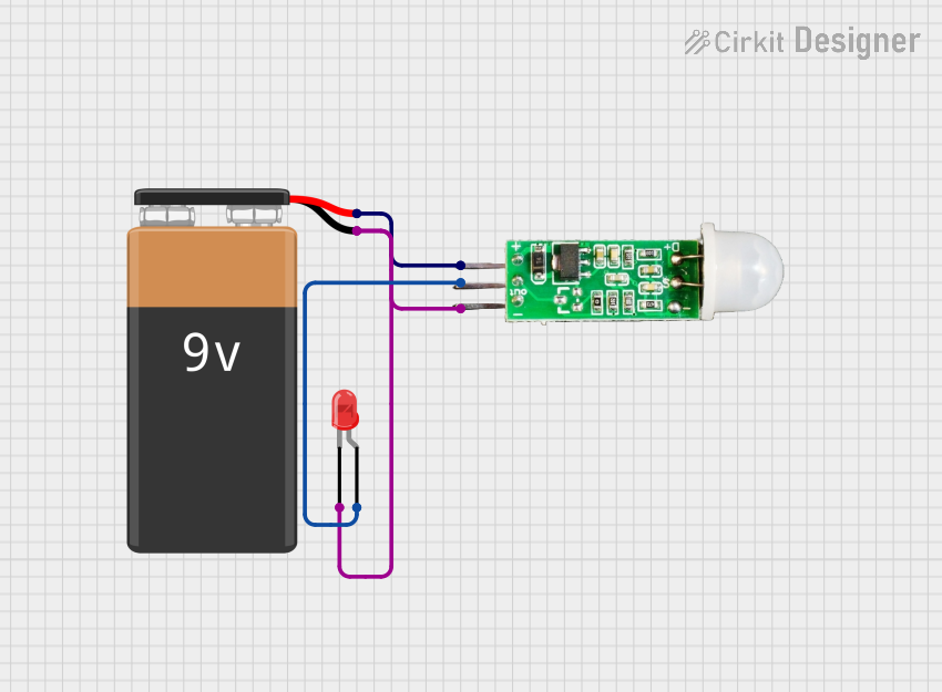
How to Use the Component in a Circuit

  1. Connect the VCC pin to a power supply within the range of 4.5V to 20V.
  2. Connect the GND pin to the ground of the power supply.
  3. Connect the OUT pin to a digital input pin on a microcontroller, such as an Arduino UNO.

Important Considerations and Best Practices

  • Ensure that the power supply voltage does not exceed the maximum rating of 20V.
  • Avoid placing the sensor in an environment with rapid temperature changes to prevent false triggers.
  • The sensor should not be exposed to direct sunlight or placed near heating devices.
  • Install the sensor away from wind sources such as air conditioners or fans.

Example Code for Arduino UNO

// Define the PIR motion sensor pin
const int PIRPin = 2; // Connect HC-SR505 OUT pin to Arduino pin 2

void setup() {
  pinMode(PIRPin, INPUT); // Set the PIR pin as an INPUT
  Serial.begin(9600); // Initialize serial communication
}

void loop() {
  int motionState = digitalRead(PIRPin); // Read the PIR sensor output
  if (motionState == HIGH) {
    // If motion is detected, output a message
    Serial.println("Motion detected!");
    // Add your code here to handle the motion event
  } else {
    // If no motion is detected, output a different message
    Serial.println("No motion.");
  }
  delay(1000); // Wait for 1 second before reading again
}

Troubleshooting and FAQs

Common Issues Users Might Face

  • False triggers: Adjust the sensor's placement or orientation to minimize false triggers caused by environmental factors.
  • No response: Check the power supply and connections to ensure the module is properly powered and connected.
  • Intermittent operation: Ensure that the sensor is not exposed to direct sunlight or strong RF fields which may cause interference.

Solutions and Tips for Troubleshooting

  • If the sensor is not triggering, verify that the connections are correct and the power supply is within the specified range.
  • In case of erratic behavior, reset the power to the module to clear any latched states.
  • For issues with sensitivity or detection range, consider adjusting the sensor's position or the delay time if applicable.

FAQs

Q: Can the HC-SR505 be used outdoors? A: The HC-SR505 is not waterproof and is best used indoors or in a protected outdoor environment.

Q: How can I adjust the delay time? A: The default delay time is approximately 8 seconds. To adjust it, you would need to replace the onboard timing resistor with one of a different value, which requires soldering and an understanding of the module's circuitry.

Q: Is it possible to power the HC-SR505 with a battery? A: Yes, as long as the battery voltage is within the 4.5V to 20V range, the HC-SR505 can be battery-powered.

Q: How can I reduce power consumption for battery-operated projects? A: You can reduce power consumption by using a lower supply voltage within the acceptable range and by minimizing the active time of any connected devices triggered by the sensor.