Cirkit Designer Logo
Cirkit Designer
Your all-in-one circuit design IDE
Home / 
Component Documentation

How to Use RAK16000 WisBlock DC Current Module: Examples, Pinouts, and Specs

Image of RAK16000 WisBlock DC Current Module
Cirkit Designer LogoDesign with RAK16000 WisBlock DC Current Module in Cirkit Designer

Introduction

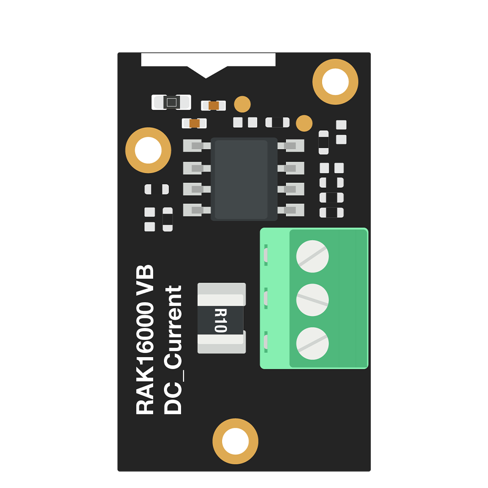
The RAK16000 WisBlock DC Current Module is a compact and versatile module designed to measure direct current (DC) in a wide range of applications. It provides accurate current readings, making it ideal for monitoring and control in electronic circuits. This module is part of the WisBlock ecosystem, which allows for seamless integration with other WisBlock modules and baseboards.

Explore Projects Built with RAK16000 WisBlock DC Current Module

Use Cirkit Designer to design, explore, and prototype these projects online. Some projects support real-time simulation. Click "Open Project" to start designing instantly!
DC-DC Converter and Relay Module Power Distribution System
Image of relay: A project utilizing RAK16000 WisBlock DC Current Module in a practical application
This circuit consists of a DC-DC converter powering a 6-channel power module, which in turn supplies 5V to a 2-relay module. The power module distributes the converted voltage to the relay module, enabling it to control external devices.
Cirkit Designer LogoOpen Project in Cirkit Designer
Cellular-Enabled IoT Device with Real-Time Clock and Power Management
Image of LRCM PHASE 2 BASIC: A project utilizing RAK16000 WisBlock DC Current Module in a practical application
This circuit features a LilyGo-SIM7000G module for cellular communication and GPS functionality, interfaced with an RTC DS3231 for real-time clock capabilities. It includes voltage sensing through two voltage sensor modules, and uses an 8-channel opto-coupler for isolating different parts of the circuit. Power management is handled by a buck converter connected to a DC power source and batteries, with a fuse for protection and a rocker switch for on/off control. Additionally, there's an LED for indication purposes.
Cirkit Designer LogoOpen Project in Cirkit Designer
ESP32C3 and SIM800L Powered Smart Energy Monitor with OLED Display and Wi-Fi Connectivity
Image of SERVER: A project utilizing RAK16000 WisBlock DC Current Module in a practical application
This circuit is a power monitoring system that uses an ESP32C3 microcontroller to collect power usage data from slave devices via WiFi and SMS. The collected data is displayed on a 0.96" OLED screen, and the system is powered by an AC-DC converter module. Additionally, the circuit includes a SIM800L GSM module for SMS communication and LEDs for status indication.
Cirkit Designer LogoOpen Project in Cirkit Designer
ESP32-Based Smart Energy Monitoring and Control System
Image of SMART SOCKET: A project utilizing RAK16000 WisBlock DC Current Module in a practical application
This circuit is designed to monitor AC voltage and current using ZMPT101B and ZMCT103C sensors, respectively, with an ESP32 microcontroller processing the sensor outputs. The XL4015 step-down module regulates the power supply to provide a stable voltage to the sensors, the ESP32, and an LCD I2C display. The ESP32 controls a 4-channel relay module for switching AC loads, and the system's operation can be interacted with via the LCD display and a push switch.
Cirkit Designer LogoOpen Project in Cirkit Designer

Explore Projects Built with RAK16000 WisBlock DC Current Module

Use Cirkit Designer to design, explore, and prototype these projects online. Some projects support real-time simulation. Click "Open Project" to start designing instantly!
Image of relay: A project utilizing RAK16000 WisBlock DC Current Module in a practical application
DC-DC Converter and Relay Module Power Distribution System
This circuit consists of a DC-DC converter powering a 6-channel power module, which in turn supplies 5V to a 2-relay module. The power module distributes the converted voltage to the relay module, enabling it to control external devices.
Cirkit Designer LogoOpen Project in Cirkit Designer
Image of LRCM PHASE 2 BASIC: A project utilizing RAK16000 WisBlock DC Current Module in a practical application
Cellular-Enabled IoT Device with Real-Time Clock and Power Management
This circuit features a LilyGo-SIM7000G module for cellular communication and GPS functionality, interfaced with an RTC DS3231 for real-time clock capabilities. It includes voltage sensing through two voltage sensor modules, and uses an 8-channel opto-coupler for isolating different parts of the circuit. Power management is handled by a buck converter connected to a DC power source and batteries, with a fuse for protection and a rocker switch for on/off control. Additionally, there's an LED for indication purposes.
Cirkit Designer LogoOpen Project in Cirkit Designer
Image of SERVER: A project utilizing RAK16000 WisBlock DC Current Module in a practical application
ESP32C3 and SIM800L Powered Smart Energy Monitor with OLED Display and Wi-Fi Connectivity
This circuit is a power monitoring system that uses an ESP32C3 microcontroller to collect power usage data from slave devices via WiFi and SMS. The collected data is displayed on a 0.96" OLED screen, and the system is powered by an AC-DC converter module. Additionally, the circuit includes a SIM800L GSM module for SMS communication and LEDs for status indication.
Cirkit Designer LogoOpen Project in Cirkit Designer
Image of SMART SOCKET: A project utilizing RAK16000 WisBlock DC Current Module in a practical application
ESP32-Based Smart Energy Monitoring and Control System
This circuit is designed to monitor AC voltage and current using ZMPT101B and ZMCT103C sensors, respectively, with an ESP32 microcontroller processing the sensor outputs. The XL4015 step-down module regulates the power supply to provide a stable voltage to the sensors, the ESP32, and an LCD I2C display. The ESP32 controls a 4-channel relay module for switching AC loads, and the system's operation can be interacted with via the LCD display and a push switch.
Cirkit Designer LogoOpen Project in Cirkit Designer

Common Applications and Use Cases

  • Battery monitoring in IoT devices
  • Power consumption measurement in embedded systems
  • Current sensing in renewable energy systems
  • Industrial automation and control
  • Electric vehicle (EV) current monitoring

Technical Specifications

The RAK16000 module is built to deliver precise current measurements while maintaining ease of use. Below are its key technical details:

Key Technical Details

Parameter Specification
Input Voltage Range 3.3V to 5V (via WisBlock Baseboard)
Current Measurement Range ±5A
Measurement Resolution 12-bit ADC
Communication Interface I2C
Operating Temperature -40°C to +85°C
Dimensions 25mm x 25mm

Pin Configuration and Descriptions

The RAK16000 module connects to the WisBlock Baseboard via the standard WisBlock interface. Below is the pin configuration:

Pin Name Description Notes
VCC Power Supply (3.3V/5V) Provided by the WisBlock Baseboard
GND Ground Common ground
SDA I2C Data Line Connects to the I2C bus
SCL I2C Clock Line Connects to the I2C bus
IN+ Positive Current Input Connect to the positive side of the load
IN- Negative Current Input Connect to the negative side of the load

Usage Instructions

The RAK16000 module is easy to integrate into your project. Follow the steps below to use it effectively:

How to Use the Component in a Circuit

  1. Connect the Module to the WisBlock Baseboard:
    • Attach the RAK16000 module to the WisBlock Baseboard using the designated slot.
  2. Connect the Current Path:
    • Connect the positive side of the load to the IN+ pin and the negative side to the IN- pin.
  3. Power the Module:
    • Ensure the WisBlock Baseboard is powered with a 3.3V or 5V supply.
  4. Establish I2C Communication:
    • Connect the SDA and SCL pins to the I2C bus of your microcontroller or WisBlock Core module.

Important Considerations and Best Practices

  • Current Range: Ensure the current flowing through the module does not exceed ±5A to avoid damage.
  • I2C Address: The default I2C address of the RAK16000 is 0x40. Verify that no other devices on the I2C bus share the same address.
  • Calibration: For precise measurements, calibrate the module as per your application requirements.
  • Noise Reduction: Use proper decoupling capacitors and shielded cables to minimize noise in high-current applications.

Example Code for Arduino UNO

The RAK16000 can be interfaced with an Arduino UNO using the I2C protocol. Below is an example code snippet:

#include <Wire.h>

// Define the I2C address of the RAK16000 module
#define RAK16000_I2C_ADDRESS 0x40

void setup() {
  // Initialize serial communication for debugging
  Serial.begin(9600);
  
  // Initialize the I2C communication
  Wire.begin();
  
  Serial.println("RAK16000 DC Current Module Initialized");
}

void loop() {
  // Request 2 bytes of data from the RAK16000 module
  Wire.beginTransmission(RAK16000_I2C_ADDRESS);
  Wire.write(0x00); // Command to read current data
  Wire.endTransmission();
  
  Wire.requestFrom(RAK16000_I2C_ADDRESS, 2);
  
  if (Wire.available() == 2) {
    // Read the two bytes of current data
    uint8_t msb = Wire.read();
    uint8_t lsb = Wire.read();
    
    // Combine the bytes into a 16-bit value
    int16_t currentRaw = (msb << 8) | lsb;
    
    // Convert the raw value to current in amperes
    float current = currentRaw * 0.001; // Assuming 1mA resolution
    
    // Print the current value
    Serial.print("Current: ");
    Serial.print(current);
    Serial.println(" A");
  }
  
  delay(1000); // Wait for 1 second before the next reading
}

Troubleshooting and FAQs

Common Issues and Solutions

  1. No Data from the Module:

    • Cause: Incorrect I2C address or wiring.
    • Solution: Verify the I2C address and ensure proper connections for SDA and SCL.
  2. Inaccurate Current Readings:

    • Cause: Calibration not performed or excessive noise in the circuit.
    • Solution: Perform calibration and use proper shielding and decoupling techniques.
  3. Module Overheating:

    • Cause: Current exceeding the ±5A limit.
    • Solution: Ensure the current through the module is within the specified range.
  4. I2C Communication Errors:

    • Cause: Conflicts with other devices on the I2C bus.
    • Solution: Check for address conflicts and ensure proper pull-up resistors are used.

FAQs

Q1: Can the RAK16000 measure AC current?
A1: No, the RAK16000 is designed specifically for DC current measurement.

Q2: What is the resolution of the current measurement?
A2: The module provides a 12-bit resolution, allowing for precise current readings.

Q3: Can I use the RAK16000 with a 5V microcontroller?
A3: Yes, the module supports both 3.3V and 5V logic levels.

Q4: How do I change the I2C address of the module?
A4: The I2C address is fixed at 0x40 and cannot be changed.

By following this documentation, you can effectively integrate the RAK16000 WisBlock DC Current Module into your projects for accurate and reliable current measurements.