How to Use Adafruit Perma Proto for Pi Full Size: Examples, Pinouts, and Specs
Introduction
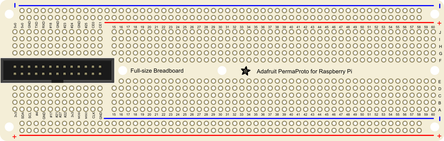
The Adafruit Perma Proto for Pi Full Size is a versatile and durable prototyping board designed for use with the Raspberry Pi 3 and Raspberry Pi 4. This board allows hobbyists, educators, and professionals to create custom circuits and projects that can be easily integrated with the Raspberry Pi platform. Its layout is similar to a standard breadboard, with interconnected holes that make it simple to add components and create complex electronic systems.
Explore Projects Built with Adafruit Perma Proto for Pi Full Size

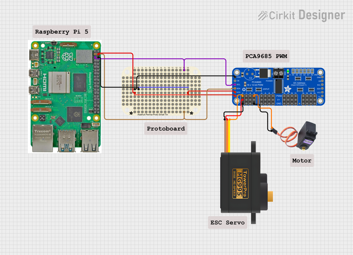
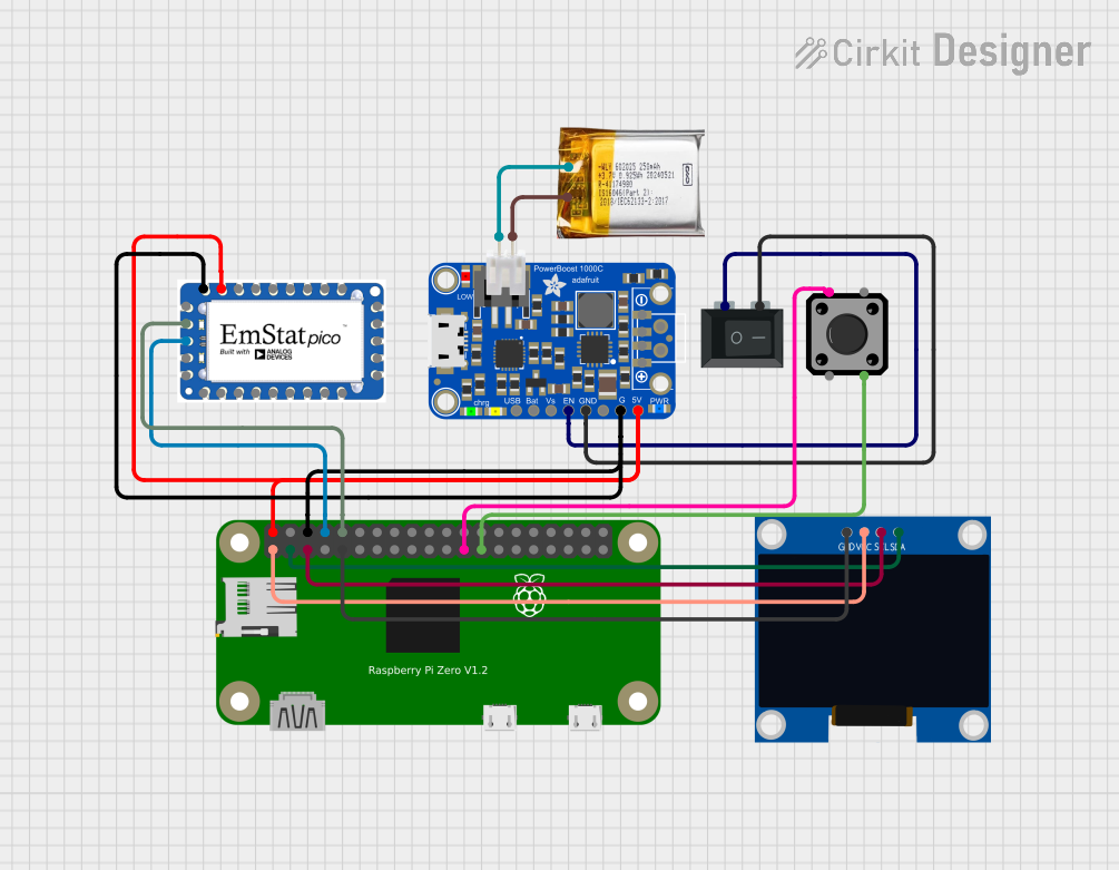
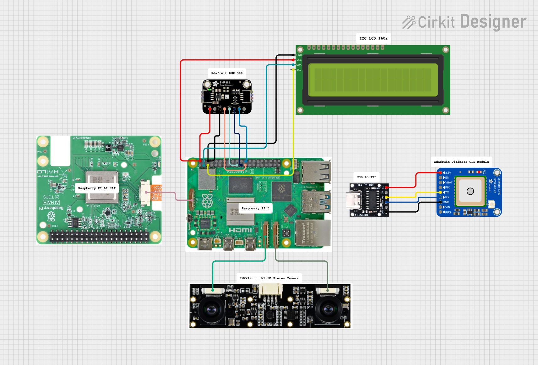
Explore Projects Built with Adafruit Perma Proto for Pi Full Size
Common Applications and Use Cases
- Prototyping Raspberry Pi-based projects
- Educational tools for teaching electronics
- Permanent circuit creation for embedded systems
- DIY home automation systems
- Robotics and custom sensor interfaces
Technical Specifications
Key Technical Details
- Compatibility: Raspberry Pi 3, Raspberry Pi 4
- Dimensions: 114mm x 79mm x 2mm
- Weight: 30g
- Material: High-quality FR4
- Hole Pitch: Standard 0.1" (2.54mm)
- Hole Diameter: 1mm (fits up to 20 AWG wire)
- Power Rails: 4 power rails with positive/negative markings
Pin Configuration and Descriptions
| Pin Number | Description | Connection Type |
|---|---|---|
| 1-40 | Corresponds to Raspberry Pi GPIO | Directly mapped to Pi GPIO pins |
| A-J | Prototyping Columns | Standard breadboard column layout |
| 1-30 | Prototyping Rows | Standard breadboard row layout |
| + | Positive Power Rail | For power distribution |
| - | Negative Power Rail | For ground distribution |
Usage Instructions
How to Use the Component in a Circuit
Planning Your Circuit:
- Begin by designing your circuit on paper or using electronic design software.
- Identify the components you will need and their connections to the Raspberry Pi GPIO pins.
Setting Up the Perma Proto Board:
- Place the Perma Proto board next to your Raspberry Pi.
- Use jumper wires to connect the GPIO pins from the Raspberry Pi to the corresponding pins on the Perma Proto board.
Adding Components:
- Insert your electronic components into the prototyping area of the Perma Proto board.
- Use soldering iron and solder to make permanent connections between components and the board.
Powering the Circuit:
- Connect the power and ground rails to the Raspberry Pi's 5V and GND pins, respectively.
- Ensure that all power connections are secure and that there is no risk of short circuits.
Important Considerations and Best Practices
- Soldering: Make sure to solder in a well-ventilated area and use proper safety equipment.
- Component Placement: Plan the layout of your components to minimize crossing wires and to ensure a clean, organized circuit.
- Testing: Before applying power, double-check all connections with a multimeter to prevent damage to the Raspberry Pi or components.
- Documentation: Keep a record of your circuit design and changes for future reference and troubleshooting.
Troubleshooting and FAQs
Common Issues Users Might Face
- Loose Connections: Ensure all components and wires are soldered properly.
- Short Circuits: Check for accidental connections that could cause shorts.
- Incorrect Wiring: Verify that all connections match your circuit design.
Solutions and Tips for Troubleshooting
- Multimeter Testing: Use a multimeter to check for continuity and correct voltages across your circuit.
- Visual Inspection: Look for any solder bridges or components that are not properly seated.
- Incremental Building: Build your circuit in stages, testing each part before adding the next component.
FAQs
Q: Can I reuse the Perma Proto board? A: The Perma Proto board is designed for permanent projects. Once components are soldered, they are not meant to be removed.
Q: Is the Perma Proto board compatible with other Raspberry Pi models? A: The board is designed for the Raspberry Pi 3 and 4, but it may be used with other models if the GPIO pinout is compatible.
Q: How do I connect components that require a different voltage than the Raspberry Pi provides? A: You will need to supply an external power source for components requiring different voltages. Make sure to connect the ground of that power source to the Raspberry Pi's ground.
For further assistance or questions, please refer to the Adafruit support forums or contact Adafruit customer service.