How to Use Radar Sensor: Examples, Pinouts, and Specs
Introduction
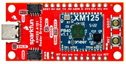
The Sparkfun Acconeer XM125 is a compact and highly versatile radar sensor module designed to detect the distance, speed, and angle of objects using radio waves. This advanced sensor is ideal for applications requiring precise object detection and motion tracking. Its small form factor and robust performance make it suitable for a wide range of industries, including automotive, aviation, robotics, and IoT.
Explore Projects Built with Radar Sensor

Explore Projects Built with Radar Sensor
Common Applications and Use Cases
- Automotive: Collision avoidance, blind-spot detection, and parking assistance.
- Aviation: Navigation and obstacle detection for drones and aircraft.
- Robotics: Object tracking and proximity sensing for autonomous systems.
- IoT: Smart home devices, security systems, and presence detection.
- Industrial: Level sensing, material monitoring, and conveyor belt systems.
Technical Specifications
The following table outlines the key technical details of the Sparkfun Acconeer XM125 radar sensor:
| Parameter | Value |
|---|---|
| Operating Voltage | 3.3V |
| Power Consumption | 1.65 mW (typical) |
| Frequency Range | 60 GHz |
| Detection Range | 0.1 m to 10 m |
| Angular Resolution | ±15° |
| Communication Interface | UART, SPI |
| Operating Temperature | -40°C to +85°C |
| Dimensions | 33 mm x 15 mm |
Pin Configuration and Descriptions
The Sparkfun Acconeer XM125 features a 10-pin interface for power, communication, and control. The pinout is as follows:
| Pin Number | Pin Name | Description |
|---|---|---|
| 1 | VCC | Power supply input (3.3V) |
| 2 | GND | Ground |
| 3 | TX | UART Transmit |
| 4 | RX | UART Receive |
| 5 | SPI_MOSI | SPI Master Out Slave In |
| 6 | SPI_MISO | SPI Master In Slave Out |
| 7 | SPI_SCK | SPI Clock |
| 8 | SPI_CS | SPI Chip Select |
| 9 | GPIO1 | General Purpose Input/Output 1 |
| 10 | GPIO2 | General Purpose Input/Output 2 |
Usage Instructions
How to Use the Component in a Circuit
- Power Supply: Connect the VCC pin to a 3.3V power source and the GND pin to ground.
- Communication Interface: Choose between UART or SPI for communication:
- For UART, connect the TX and RX pins to the corresponding UART pins on your microcontroller.
- For SPI, connect the SPI_MOSI, SPI_MISO, SPI_SCK, and SPI_CS pins to the respective SPI pins on your microcontroller.
- GPIO Pins: Use GPIO1 and GPIO2 for additional control or status signaling as needed.
- Antenna Placement: Ensure the sensor's antenna has a clear line of sight to the target for optimal performance.
Important Considerations and Best Practices
- Power Supply: Use a stable 3.3V power source to avoid damage to the sensor.
- Interference: Avoid placing the sensor near other high-frequency devices to minimize interference.
- Mounting: Position the sensor securely and ensure it is oriented correctly for the desired detection area.
- Firmware: Update the sensor's firmware to the latest version for improved performance and features.
Example Code for Arduino UNO
Below is an example of how to interface the Sparkfun Acconeer XM125 with an Arduino UNO using UART communication:
#include <SoftwareSerial.h>

// Define the UART pins for the radar sensor
#define RADAR_TX 2  // Radar sensor TX connected to Arduino pin 2
#define RADAR_RX 3  // Radar sensor RX connected to Arduino pin 3

// Create a SoftwareSerial object for communication
SoftwareSerial radarSerial(RADAR_RX, RADAR_TX);

void setup() {
  // Initialize serial communication with the radar sensor
  radarSerial.begin(115200); // Radar sensor baud rate
  Serial.begin(9600);        // Serial monitor baud rate

  Serial.println("Radar Sensor Initialized");
}

void loop() {
  // Check if data is available from the radar sensor
  if (radarSerial.available()) {
    String radarData = radarSerial.readString(); // Read data from the sensor
    Serial.println("Radar Data: " + radarData); // Print data to the serial monitor
  }

  delay(100); // Small delay to avoid overwhelming the serial buffer
}
Troubleshooting and FAQs
Common Issues and Solutions
No Data from the Sensor
- Cause: Incorrect wiring or communication settings.
- Solution: Double-check the connections and ensure the UART or SPI settings match the sensor's configuration.
Inconsistent Readings
- Cause: Interference from nearby devices or obstacles in the detection path.
- Solution: Relocate the sensor to a less noisy environment and ensure a clear line of sight.
Sensor Overheating
- Cause: Prolonged operation in high-temperature environments.
- Solution: Ensure adequate ventilation and operate within the specified temperature range (-40°C to +85°C).
Firmware Update Issues
- Cause: Interrupted update process or incompatible firmware version.
- Solution: Retry the update process and ensure the correct firmware file is used.
FAQs
Q: Can the sensor detect multiple objects simultaneously?
A: Yes, the sensor can detect multiple objects within its range and provide their relative positions.Q: What is the maximum detection range of the sensor?
A: The sensor can detect objects up to 10 meters away.Q: Can the sensor be used outdoors?
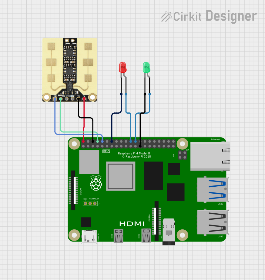
A: Yes, the sensor is designed to operate in a wide temperature range and can be used outdoors, but it should be protected from direct exposure to water or extreme environmental conditions.Q: Is the sensor compatible with Raspberry Pi?
A: Yes, the sensor can be interfaced with Raspberry Pi using UART or SPI communication.
This concludes the documentation for the Sparkfun Acconeer XM125 radar sensor. For further assistance, refer to the manufacturer's datasheet or support resources.