Cirkit Designer Logo
Cirkit Designer
Your all-in-one circuit design IDE
Home / 
Component Documentation

How to Use IO expander: Examples, Pinouts, and Specs

Image of IO expander
Cirkit Designer LogoDesign with IO expander in Cirkit Designer

Introduction

The PCF8575 is a 16-bit I/O expander from Adafruit that provides additional digital input and output pins for microcontrollers with limited I/O capabilities. It communicates with the host microcontroller via the I2C bus, allowing for the control of up to 16 additional digital devices. Common applications include expanding the number of I/O pins on microcontrollers, such as the Arduino UNO, for use in projects that require multiple sensors, buttons, LEDs, or other digital devices.

Explore Projects Built with IO expander

Use Cirkit Designer to design, explore, and prototype these projects online. Some projects support real-time simulation. Click "Open Project" to start designing instantly!
I2C-Controlled Relay Switching with ESP32 and MCP23017 for Home Automation
Image of Vloerverwarming: A project utilizing IO expander in a practical application
This circuit appears to be a control system utilizing two MCP23017 I/O expanders interfaced with an Olimex ESP32-EVB microcontroller via I2C communication, as indicated by the SDA and SCL connections with pull-up resistors. The MCP23017 expanders control an 8-channel relay module, allowing the microcontroller to switch various loads, potentially for home automation or industrial control. Additionally, there is an Adafruit ADS1115 16-bit ADC for analog signal measurement, and several heating actuators and a thermostat are connected, suggesting temperature control functionality.
Cirkit Designer LogoOpen Project in Cirkit Designer
ESP32-Based Industrial Control System with RS485 Communication and I2C Interface
Image of DRIVER TESTER : A project utilizing IO expander in a practical application
This circuit integrates a microcontroller with a display, digital potentiometer, IO expander, and opto-isolator board for signal interfacing and isolation. It includes a UART to RS485 converter for serial communication and a power converter to step down voltage for the system. The circuit is designed for control and communication in an isolated and protected environment.
Cirkit Designer LogoOpen Project in Cirkit Designer
ESP32-Based I2C Communication Hub with Multiplexer and Expander
Image of Lights: A project utilizing IO expander in a practical application
This circuit features an Olimex ESP32-EVB microcontroller unit (MCU) for processing and connectivity, interfaced with an MCP23017 I/O expander and an Adafruit TCA9548A I2C multiplexer to expand the number of I/O lines and allow multiple I2C devices to communicate with the MCU over the same bus. Pull-up resistors are connected to the I2C lines for proper bus operation, and both the MCP23017 and TCA9548A have their reset lines pulled high, likely for normal operation without external reset control.
Cirkit Designer LogoOpen Project in Cirkit Designer
Raspberry Pi and Arduino-Based Smart Home Automation System with Battery Backup
Image of final na 'to? : A project utilizing IO expander in a practical application
This circuit integrates a Raspberry Pi 4B and an Arduino UNO to control various sensors and actuators, including IR sensors, ultrasonic sensors, a water pump, and DC motors. The GPIO expander extends the Raspberry Pi's I/O capabilities, while the L298N motor driver manages the DC motors. Power management is handled by multiple buck converters and a UPS battery.
Cirkit Designer LogoOpen Project in Cirkit Designer

Explore Projects Built with IO expander

Use Cirkit Designer to design, explore, and prototype these projects online. Some projects support real-time simulation. Click "Open Project" to start designing instantly!
Image of Vloerverwarming: A project utilizing IO expander in a practical application
I2C-Controlled Relay Switching with ESP32 and MCP23017 for Home Automation
This circuit appears to be a control system utilizing two MCP23017 I/O expanders interfaced with an Olimex ESP32-EVB microcontroller via I2C communication, as indicated by the SDA and SCL connections with pull-up resistors. The MCP23017 expanders control an 8-channel relay module, allowing the microcontroller to switch various loads, potentially for home automation or industrial control. Additionally, there is an Adafruit ADS1115 16-bit ADC for analog signal measurement, and several heating actuators and a thermostat are connected, suggesting temperature control functionality.
Cirkit Designer LogoOpen Project in Cirkit Designer
Image of DRIVER TESTER : A project utilizing IO expander in a practical application
ESP32-Based Industrial Control System with RS485 Communication and I2C Interface
This circuit integrates a microcontroller with a display, digital potentiometer, IO expander, and opto-isolator board for signal interfacing and isolation. It includes a UART to RS485 converter for serial communication and a power converter to step down voltage for the system. The circuit is designed for control and communication in an isolated and protected environment.
Cirkit Designer LogoOpen Project in Cirkit Designer
Image of Lights: A project utilizing IO expander in a practical application
ESP32-Based I2C Communication Hub with Multiplexer and Expander
This circuit features an Olimex ESP32-EVB microcontroller unit (MCU) for processing and connectivity, interfaced with an MCP23017 I/O expander and an Adafruit TCA9548A I2C multiplexer to expand the number of I/O lines and allow multiple I2C devices to communicate with the MCU over the same bus. Pull-up resistors are connected to the I2C lines for proper bus operation, and both the MCP23017 and TCA9548A have their reset lines pulled high, likely for normal operation without external reset control.
Cirkit Designer LogoOpen Project in Cirkit Designer
Image of final na 'to? : A project utilizing IO expander in a practical application
Raspberry Pi and Arduino-Based Smart Home Automation System with Battery Backup
This circuit integrates a Raspberry Pi 4B and an Arduino UNO to control various sensors and actuators, including IR sensors, ultrasonic sensors, a water pump, and DC motors. The GPIO expander extends the Raspberry Pi's I/O capabilities, while the L298N motor driver manages the DC motors. Power management is handled by multiple buck converters and a UPS battery.
Cirkit Designer LogoOpen Project in Cirkit Designer

Technical Specifications

Key Technical Details

  • Supply Voltage (Vcc): 2.5V to 5.5V
  • I2C Bus Voltage: 5V tolerant
  • Output Current per I/O pin: 25 mA
  • Total Output Current: 400 mA
  • Input Leakage Current: ±1 µA (max)
  • Operating Temperature Range: -40°C to +85°C

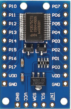
Pin Configuration and Descriptions

Pin Number Pin Name Description
1 A0 Address pin 0, used to set the I2C address
2 A1 Address pin 1, used to set the I2C address
3 A2 Address pin 2, used to set the I2C address
4 P0 I/O port 0
5 P1 I/O port 1
... ... ...
19 P16 I/O port 16
20 Vss Ground (0V)
21 SDA I2C Data Line
22 SCL I2C Clock Line
23 INT Interrupt Output (active low)
24 Vcc Supply Voltage

Usage Instructions

Connecting to a Microcontroller

  1. Connect Vcc to the microcontroller's 5V power output.
  2. Connect Vss to the microcontroller's ground.
  3. Connect SDA and SCL to the microcontroller's I2C data and clock pins respectively.
  4. Use pull-up resistors on the SDA and SCL lines if they are not already present on the microcontroller board.
  5. Set the A0, A1, and A2 pins to either high or low to establish a unique I2C address if multiple I2C devices are used.

Programming with Arduino UNO

Here is an example code snippet for initializing the PCF8575 and toggling all pins:

#include <Wire.h>

// PCF8575 I2C address is 0x20(32) if A0, A1, and A2 are connected to GND
#define PCF8575_ADDRESS 0x20

void setup() {
  Wire.begin(); // Initialize I2C communications as Master
}

void loop() {
  // Write all pins high
  Wire.beginTransmission(PCF8575_ADDRESS);
  Wire.write(0xFF); // Low byte
  Wire.write(0xFF); // High byte
  Wire.endTransmission();
  delay(1000);

  // Write all pins low
  Wire.beginTransmission(PCF8575_ADDRESS);
  Wire.write(0x00); // Low byte
  Wire.write(0x00); // High byte
  Wire.endTransmission();
  delay(1000);
}

Important Considerations and Best Practices

  • Ensure that the I2C address of the PCF8575 does not conflict with other I2C devices on the bus.
  • Use appropriate pull-up resistors on the I2C lines (typically 4.7kΩ to 10kΩ).
  • Avoid exceeding the maximum current ratings for each I/O pin and the total output current.
  • Consider using the interrupt pin (INT) to detect input changes without polling the device.

Troubleshooting and FAQs

Common Issues

  • I2C Communication Failure: Check connections, ensure pull-up resistors are installed, and verify that there are no address conflicts.
  • Unexpected Behavior on I/O Pins: Ensure that the pins are properly configured as inputs or outputs in your code.

Solutions and Tips for Troubleshooting

  • Use I2C scanner code to confirm the PCF8575 is detected on the I2C bus.
  • Check the power supply voltage and ground connections.
  • Use a multimeter to verify the logic levels on the I2C lines.

FAQs

Q: Can I use the PCF8575 with a 3.3V microcontroller? A: Yes, the PCF8575 is compatible with 3.3V logic levels, but ensure that the I2C bus voltage matches the microcontroller's logic level.

Q: How many PCF8575 expanders can I connect to a single I2C bus? A: You can connect up to 8 PCF8575 devices on a single I2C bus by configuring the A0, A1, and A2 pins for different addresses.

Q: What is the purpose of the interrupt pin? A: The interrupt pin can be used to alert the microcontroller when an input state has changed, allowing for more efficient monitoring of the I/O pins.

This documentation provides a comprehensive guide to using the Adafruit PCF8575 I/O expander. For further assistance, consult the manufacturer's datasheet and technical support resources.