How to Use T-Cobbler Plus - GPIO Breakout: Examples, Pinouts, and Specs
Introduction
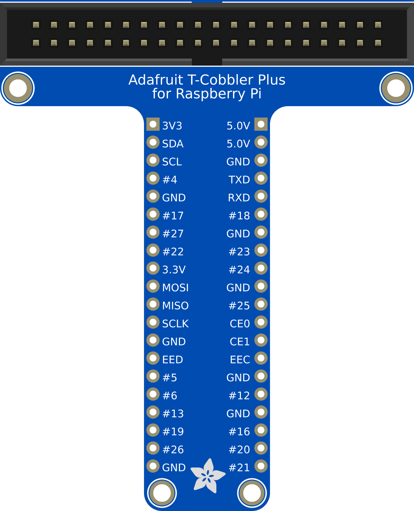
The T-Cobbler Plus is a GPIO breakout board designed for the Raspberry Pi. It provides an easy and convenient way to access the Raspberry Pi's GPIO pins for prototyping and development. By connecting the T-Cobbler Plus to a breadboard, users can quickly and efficiently interface with various sensors, actuators, and other electronic components.
Explore Projects Built with T-Cobbler Plus - GPIO Breakout

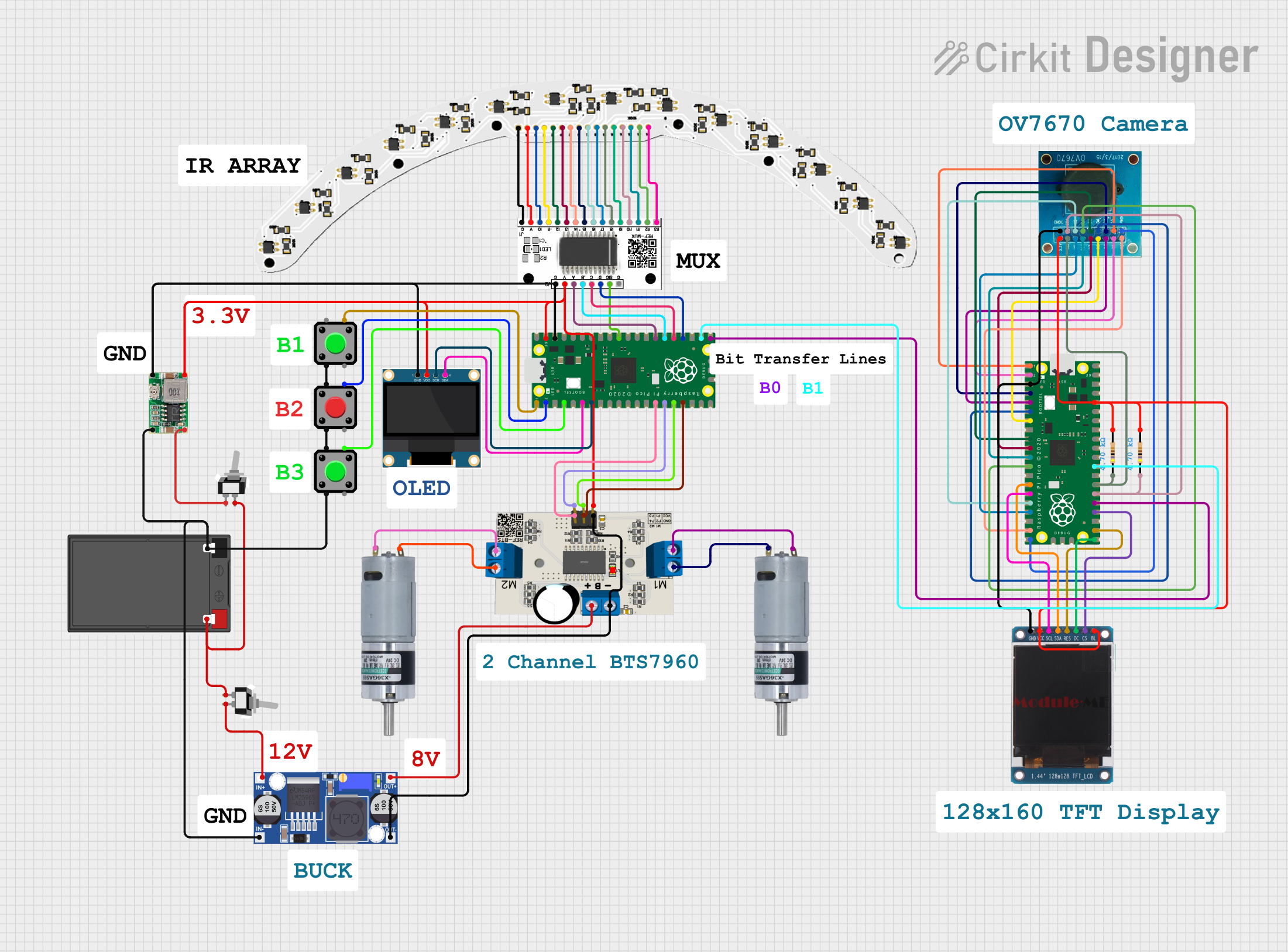

Explore Projects Built with T-Cobbler Plus - GPIO Breakout
Common Applications and Use Cases
- Prototyping and Development: Ideal for experimenting with different circuits and components.
- Educational Projects: Perfect for teaching and learning about electronics and programming.
- Home Automation: Useful for creating custom home automation solutions.
- IoT Projects: Facilitates the development of Internet of Things (IoT) applications.
Technical Specifications
Key Technical Details
| Specification | Value |
|---|---|
| Compatibility | Raspberry Pi (all models) |
| GPIO Pin Count | 40 pins |
| Breadboard Support | Standard 830-point breadboard |
| Connector Type | 40-pin ribbon cable |
| Dimensions | 65mm x 58mm x 15mm |
Pin Configuration and Descriptions
| Pin Number | GPIO Pin | Description |
|---|---|---|
| 1 | 3.3V | 3.3V Power Supply |
| 2 | 5V | 5V Power Supply |
| 3 | GPIO2 | I2C SDA |
| 4 | 5V | 5V Power Supply |
| 5 | GPIO3 | I2C SCL |
| 6 | GND | Ground |
| 7 | GPIO4 | General Purpose I/O |
| 8 | GPIO14 | UART TX |
| 9 | GND | Ground |
| 10 | GPIO15 | UART RX |
| 11 | GPIO17 | General Purpose I/O |
| 12 | GPIO18 | PWM |
| 13 | GPIO27 | General Purpose I/O |
| 14 | GND | Ground |
| 15 | GPIO22 | General Purpose I/O |
| 16 | GPIO23 | General Purpose I/O |
| 17 | 3.3V | 3.3V Power Supply |
| 18 | GPIO24 | General Purpose I/O |
| 19 | GPIO10 | SPI MOSI |
| 20 | GND | Ground |
| 21 | GPIO9 | SPI MISO |
| 22 | GPIO25 | General Purpose I/O |
| 23 | GPIO11 | SPI SCLK |
| 24 | GPIO8 | SPI CE0 |
| 25 | GND | Ground |
| 26 | GPIO7 | SPI CE1 |
| 27 | ID_SD | I2C ID EEPROM |
| 28 | ID_SC | I2C ID EEPROM |
| 29 | GPIO5 | General Purpose I/O |
| 30 | GND | Ground |
| 31 | GPIO6 | General Purpose I/O |
| 32 | GPIO12 | PWM |
| 33 | GPIO13 | PWM |
| 34 | GND | Ground |
| 35 | GPIO19 | PWM |
| 36 | GPIO16 | General Purpose I/O |
| 37 | GPIO26 | General Purpose I/O |
| 38 | GPIO20 | General Purpose I/O |
| 39 | GND | Ground |
| 40 | GPIO21 | General Purpose I/O |
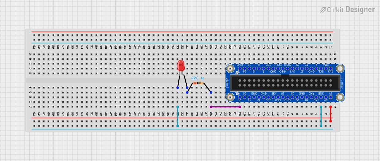
Usage Instructions
How to Use the T-Cobbler Plus in a Circuit
Connect the T-Cobbler Plus to the Raspberry Pi:
- Use a 40-pin ribbon cable to connect the T-Cobbler Plus to the GPIO header on the Raspberry Pi.
Mount the T-Cobbler Plus on a Breadboard:
- Place the T-Cobbler Plus on a standard 830-point breadboard, ensuring that the pins align with the breadboard rows.
Connect Components:
- Use jumper wires to connect sensors, actuators, and other components to the appropriate GPIO pins on the T-Cobbler Plus.
Power the Raspberry Pi:
- Ensure the Raspberry Pi is powered on and running the appropriate software to interface with the connected components.
Important Considerations and Best Practices
- Check Pinout: Always double-check the pinout to ensure correct connections.
- Use Resistors: When connecting LEDs or other components that require current limiting, use appropriate resistors.
- Avoid Short Circuits: Be cautious to avoid short circuits, which can damage the Raspberry Pi and connected components.
- Software Configuration: Ensure the Raspberry Pi is configured correctly to use the GPIO pins (e.g., using the
gpiocommand or a library likeRPi.GPIO).
Example Code
Here is an example of how to use the T-Cobbler Plus with a Raspberry Pi to blink an LED connected to GPIO17:
import RPi.GPIO as GPIO
import time
Set the GPIO mode to BCM
GPIO.setmode(GPIO.BCM)
Set up GPIO17 as an output pin
GPIO.setup(17, GPIO.OUT)
try: while True: GPIO.output(17, GPIO.HIGH) # Turn on the LED time.sleep(1) # Wait for 1 second GPIO.output(17, GPIO.LOW) # Turn off the LED time.sleep(1) # Wait for 1 second except KeyboardInterrupt: pass # Exit the loop when Ctrl+C is pressed
Clean up the GPIO settings
GPIO.cleanup()
Troubleshooting and FAQs
Common Issues Users Might Face
No Power to Components:
- Solution: Ensure the T-Cobbler Plus is securely connected to the Raspberry Pi and the breadboard. Check the power supply connections.
Incorrect GPIO Pin Mapping:
- Solution: Verify the pin mapping and ensure the correct GPIO pins are used in the code and connections.
Components Not Responding:
- Solution: Check the connections and ensure the components are functioning correctly. Use a multimeter to verify voltage levels.
Solutions and Tips for Troubleshooting
- Use a Multimeter: A multimeter can help diagnose issues by checking voltage levels and continuity.
- Check Software Configuration: Ensure the Raspberry Pi's software is correctly configured to use the GPIO pins.
- Refer to Documentation: Consult the Raspberry Pi and T-Cobbler Plus documentation for detailed information on pinouts and usage.
By following this documentation, users can effectively utilize the T-Cobbler Plus GPIO breakout board for their Raspberry Pi projects, enabling easy access to GPIO pins for a wide range of applications.