Cirkit Designer Logo
Cirkit Designer
Your all-in-one circuit design IDE
Home / 
Component Documentation

How to Use SM712: Examples, Pinouts, and Specs

Image of SM712
Cirkit Designer LogoDesign with SM712 in Cirkit Designer

Introduction

The SM712 is a bidirectional voltage clamp diode designed for overvoltage protection in electronic circuits. It safeguards sensitive components from voltage spikes by clamping the voltage to a safe, predefined level. This makes it an essential component in circuits prone to transient voltage surges, such as those caused by electrostatic discharge (ESD), lightning, or inductive load switching.

Explore Projects Built with SM712

Use Cirkit Designer to design, explore, and prototype these projects online. Some projects support real-time simulation. Click "Open Project" to start designing instantly!
Wemos S2 Mini Controlled Smart Device with OLED Display, Thermal Printing, and RGB LED Strip
Image of DT NEA - Noah Patel: A project utilizing SM712 in a practical application
This circuit features a Wemos S2 Mini microcontroller that controls a WS2812 RGB LED strip and communicates with a 0.96" OLED display and a 58mm mini thermal printer. The ACS712 Current Sensor is interfaced with the microcontroller to monitor current, and power is managed by a CD42 BMS connected to two 18650 Li-ion batteries, with a USB-C PD Trigger Board for power delivery. The circuit is designed for visual output (LED strip, OLED display), printing capabilities, and current sensing, likely for a portable, battery-powered monitoring and display device.
Cirkit Designer LogoOpen Project in Cirkit Designer
Arduino Mega 2560 Based Security System with Fingerprint Authentication and SMS Alerts
Image of Door security system: A project utilizing SM712 in a practical application
This circuit features an Arduino Mega 2560 microcontroller interfaced with a SIM800L GSM module, two fingerprint scanners, an I2C LCD display, an IR sensor, and a piezo buzzer. Power management is handled by a PowerBoost 1000 Basic Pad USB, a TP4056 charging module, and a Li-ion 18650 battery, with an option to use a Mini AC-DC 110V-230V to 5V 700mA module for direct power supply. The primary functionality appears to be a security system with GSM communication capabilities, biometric access control, and visual/audible feedback.
Cirkit Designer LogoOpen Project in Cirkit Designer
Battery-Powered Emergency Alert System with NUCLEO-F072RB, SIM800L, and GPS NEO 6M
Image of women safety: A project utilizing SM712 in a practical application
This circuit is an emergency alert system that uses a NUCLEO-F072RB microcontroller to send SMS alerts and make calls via a SIM800L GSM module, while obtaining location data from a GPS NEO 6M module. The system is powered by a Li-ion battery and includes a TP4056 module for battery charging and protection, with a rocker switch to control power to the microcontroller.
Cirkit Designer LogoOpen Project in Cirkit Designer
STM32 and ESP8266-Based Electric Grid Monitoring and Control System with I2C LCD Display
Image of electric grid monitoring: A project utilizing SM712 in a practical application
This circuit monitors and controls an electric grid by measuring voltage and current using ZMPT101B and ACS712 sensors, displaying the readings on a 16x2 I2C LCD screen, and controlling a relay module to manage the load. The system is powered by a 3.3V battery, uses an STM32 microcontroller for processing, and includes an ESP8266 module for remote monitoring and control via WiFi.
Cirkit Designer LogoOpen Project in Cirkit Designer

Explore Projects Built with SM712

Use Cirkit Designer to design, explore, and prototype these projects online. Some projects support real-time simulation. Click "Open Project" to start designing instantly!
Image of DT NEA - Noah Patel: A project utilizing SM712 in a practical application
Wemos S2 Mini Controlled Smart Device with OLED Display, Thermal Printing, and RGB LED Strip
This circuit features a Wemos S2 Mini microcontroller that controls a WS2812 RGB LED strip and communicates with a 0.96" OLED display and a 58mm mini thermal printer. The ACS712 Current Sensor is interfaced with the microcontroller to monitor current, and power is managed by a CD42 BMS connected to two 18650 Li-ion batteries, with a USB-C PD Trigger Board for power delivery. The circuit is designed for visual output (LED strip, OLED display), printing capabilities, and current sensing, likely for a portable, battery-powered monitoring and display device.
Cirkit Designer LogoOpen Project in Cirkit Designer
Image of Door security system: A project utilizing SM712 in a practical application
Arduino Mega 2560 Based Security System with Fingerprint Authentication and SMS Alerts
This circuit features an Arduino Mega 2560 microcontroller interfaced with a SIM800L GSM module, two fingerprint scanners, an I2C LCD display, an IR sensor, and a piezo buzzer. Power management is handled by a PowerBoost 1000 Basic Pad USB, a TP4056 charging module, and a Li-ion 18650 battery, with an option to use a Mini AC-DC 110V-230V to 5V 700mA module for direct power supply. The primary functionality appears to be a security system with GSM communication capabilities, biometric access control, and visual/audible feedback.
Cirkit Designer LogoOpen Project in Cirkit Designer
Image of women safety: A project utilizing SM712 in a practical application
Battery-Powered Emergency Alert System with NUCLEO-F072RB, SIM800L, and GPS NEO 6M
This circuit is an emergency alert system that uses a NUCLEO-F072RB microcontroller to send SMS alerts and make calls via a SIM800L GSM module, while obtaining location data from a GPS NEO 6M module. The system is powered by a Li-ion battery and includes a TP4056 module for battery charging and protection, with a rocker switch to control power to the microcontroller.
Cirkit Designer LogoOpen Project in Cirkit Designer
Image of electric grid monitoring: A project utilizing SM712 in a practical application
STM32 and ESP8266-Based Electric Grid Monitoring and Control System with I2C LCD Display
This circuit monitors and controls an electric grid by measuring voltage and current using ZMPT101B and ACS712 sensors, displaying the readings on a 16x2 I2C LCD screen, and controlling a relay module to manage the load. The system is powered by a 3.3V battery, uses an STM32 microcontroller for processing, and includes an ESP8266 module for remote monitoring and control via WiFi.
Cirkit Designer LogoOpen Project in Cirkit Designer

Common Applications and Use Cases

  • Protection of data lines in communication systems
  • Safeguarding industrial control systems
  • Overvoltage protection in automotive electronics
  • ESD protection for sensitive electronic devices
  • Use in power supply circuits to prevent transient damage

Technical Specifications

Key Technical Details

  • Type: Bidirectional TVS (Transient Voltage Suppressor) diode
  • Reverse Stand-Off Voltage (VRWM): ±12V
  • Breakdown Voltage (VBR): 13.3V to 14.7V
  • Clamping Voltage (VC): 19V (at 1A)
  • Peak Pulse Current (IPP): 19A (8/20µs waveform)
  • Power Dissipation (PPPM): 400W (8/20µs waveform)
  • Capacitance: 30pF (typical at VR = 0V, f = 1MHz)
  • Operating Temperature Range: -55°C to +150°C
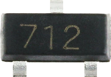
  • Package Type: SOT-23-3

Pin Configuration and Descriptions

The SM712 is available in a 3-pin SOT-23 package. The pinout is as follows:

Pin Number Pin Name Description
1 Anode 1 First anode terminal for bidirectional protection
2 Cathode Common cathode terminal
3 Anode 2 Second anode terminal for bidirectional protection

Usage Instructions

How to Use the SM712 in a Circuit

  1. Placement in the Circuit:

    • Connect the SM712 across the signal or power lines that require protection.
    • Ensure that the cathode (Pin 2) is connected to the ground or reference voltage.
    • The two anodes (Pin 1 and Pin 3) should be connected to the lines being protected.
  2. Voltage Considerations:

    • Ensure the operating voltage of the circuit does not exceed the reverse stand-off voltage (±12V).
    • If the voltage exceeds this level, the SM712 will clamp the voltage to prevent damage to the circuit.
  3. PCB Layout Recommendations:

    • Place the SM712 as close as possible to the protected device or circuit to minimize parasitic inductance.
    • Use short and wide traces for the connections to reduce resistance and improve clamping performance.
  4. Testing the Circuit:

    • After installation, test the circuit under normal operating conditions to ensure the SM712 is functioning correctly.
    • Simulate transient events (e.g., ESD or voltage spikes) to verify the clamping action.

Important Considerations and Best Practices

  • Power Dissipation: Ensure the transient energy does not exceed the power dissipation rating of 400W.
  • Capacitance Impact: The SM712 has a typical capacitance of 30pF, which may affect high-speed signal lines. Verify compatibility with your application.
  • Temperature Range: Operate the SM712 within its specified temperature range (-55°C to +150°C) to avoid performance degradation.
  • Polarity: Since the SM712 is bidirectional, it can protect against both positive and negative voltage spikes without requiring polarity-specific installation.

Example: Using the SM712 with an Arduino UNO

The SM712 can be used to protect the input/output pins of an Arduino UNO from voltage spikes. Below is an example of how to connect the SM712 to an Arduino digital input pin:

Circuit Description

  • Connect the cathode (Pin 2) of the SM712 to the Arduino GND pin.
  • Connect one anode (Pin 1 or Pin 3) to the Arduino digital input pin (e.g., D2).
  • The other anode can be left unconnected or used for bidirectional protection if needed.

Arduino Code Example

// Example code to read a digital input protected by the SM712
const int protectedPin = 2; // Digital pin connected to the SM712

void setup() {
  pinMode(protectedPin, INPUT); // Set the pin as input
  Serial.begin(9600);          // Initialize serial communication
}

void loop() {
  int pinState = digitalRead(protectedPin); // Read the state of the pin
  Serial.print("Pin State: ");             // Print the pin state to the serial monitor
  Serial.println(pinState);
  delay(500);                              // Wait for 500ms before the next read
}

Troubleshooting and FAQs

Common Issues and Solutions

  1. Issue: The SM712 is not clamping voltage spikes effectively.
    Solution: Verify that the operating voltage does not exceed the reverse stand-off voltage (±12V). Check for proper placement and soldering of the SM712 in the circuit.

  2. Issue: High-speed signals are distorted when using the SM712.
    Solution: The capacitance of the SM712 (30pF) may be affecting the signal integrity. Consider using a TVS diode with lower capacitance for high-speed applications.

  3. Issue: The SM712 overheats during operation.
    Solution: Ensure the transient energy does not exceed the power dissipation rating of 400W. Check for proper thermal management and reduce the frequency or magnitude of transient events if possible.

  4. Issue: The circuit is not functioning after installing the SM712.
    Solution: Double-check the pin connections. Ensure the cathode (Pin 2) is connected to the ground and the anodes (Pin 1 and Pin 3) are connected to the protected lines.

FAQs

Q1: Can the SM712 protect against lightning surges?
A1: Yes, the SM712 can protect against lightning-induced surges, provided the surge energy does not exceed its power dissipation rating of 400W.

Q2: Is the SM712 suitable for AC circuits?
A2: Yes, the SM712 is bidirectional and can be used in AC circuits for overvoltage protection.

Q3: Can I use the SM712 for USB port protection?
A3: The SM712 can be used for USB protection, but its capacitance (30pF) may affect high-speed USB signals. Verify compatibility with your specific USB application.

Q4: How do I test if the SM712 is working?
A4: Apply a controlled voltage spike to the protected circuit and measure the clamping voltage across the SM712. It should clamp the voltage to approximately 19V.