The LPA2172 is a high-performance audio amplifier integrated circuit (IC) manufactured by LPS. It is designed to deliver both low and high power output, making it suitable for a wide range of audio applications. The LPA2172 is optimized for driving speakers with high efficiency and excellent sound quality, ensuring minimal distortion and low power consumption.
Explore Projects Built with integrado LPA2172 Amplificador de audio baja y alta potencia
Use Cirkit Designer to design, explore, and prototype these projects online. Some projects support real-time simulation. Click "Open Project" to start designing instantly!
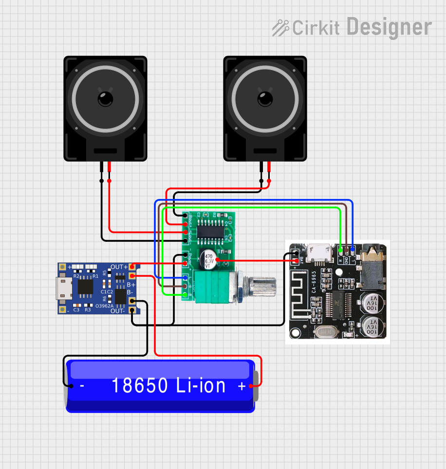
This circuit is a Bluetooth-enabled audio system powered by a rechargeable 18650 Li-ion battery. It includes a TP4056 module for battery charging and protection, a PAM8403 amplifier with volume control to drive two loudspeakers, and a Bluetooth audio receiver to wirelessly receive audio signals.
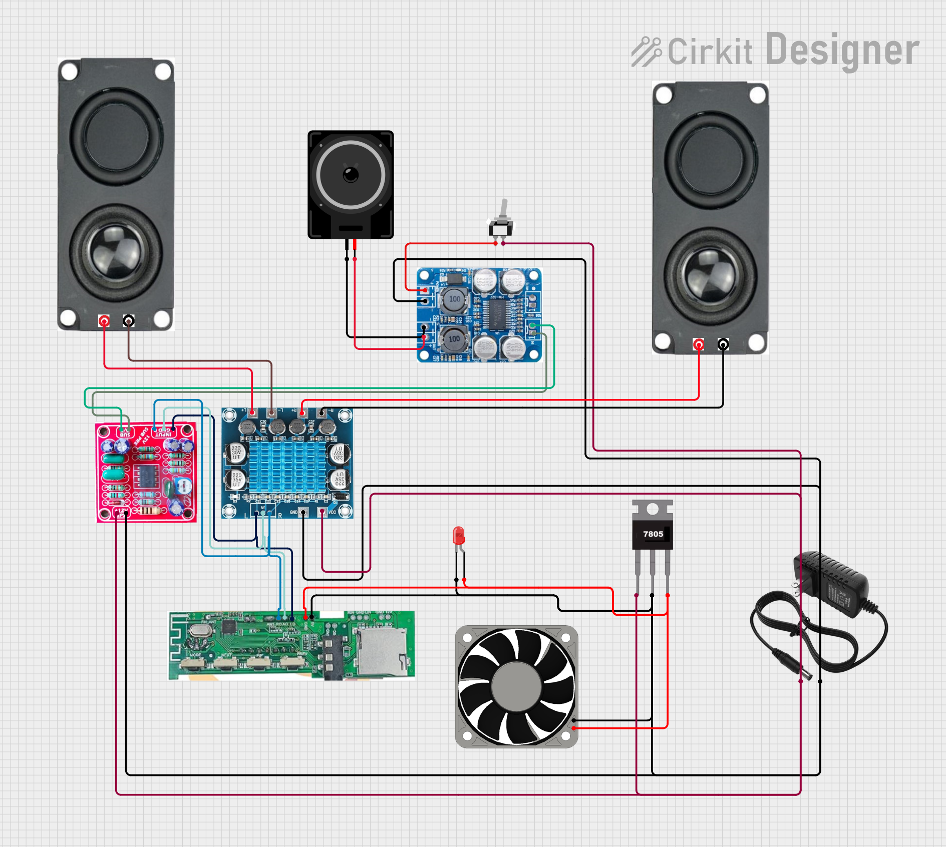
This circuit is a Bluetooth-enabled audio amplifier system with a subwoofer pre-amp and dual 8-ohm speakers. It includes a 12V power supply, a 7805 voltage regulator, and a cooling fan, with a toggle switch to control power. The Bluetooth module provides audio input to the amplifiers, which drive the speakers and subwoofer.
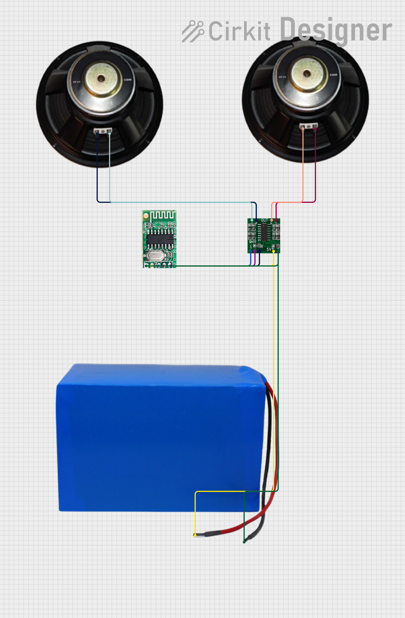
This circuit is a Bluetooth audio amplifier system powered by a 38.5V battery. It uses a 5V Bluetooth audio receiver to receive audio signals, which are then amplified by a PAM8403 amplifier and output to two speakers for stereo sound.
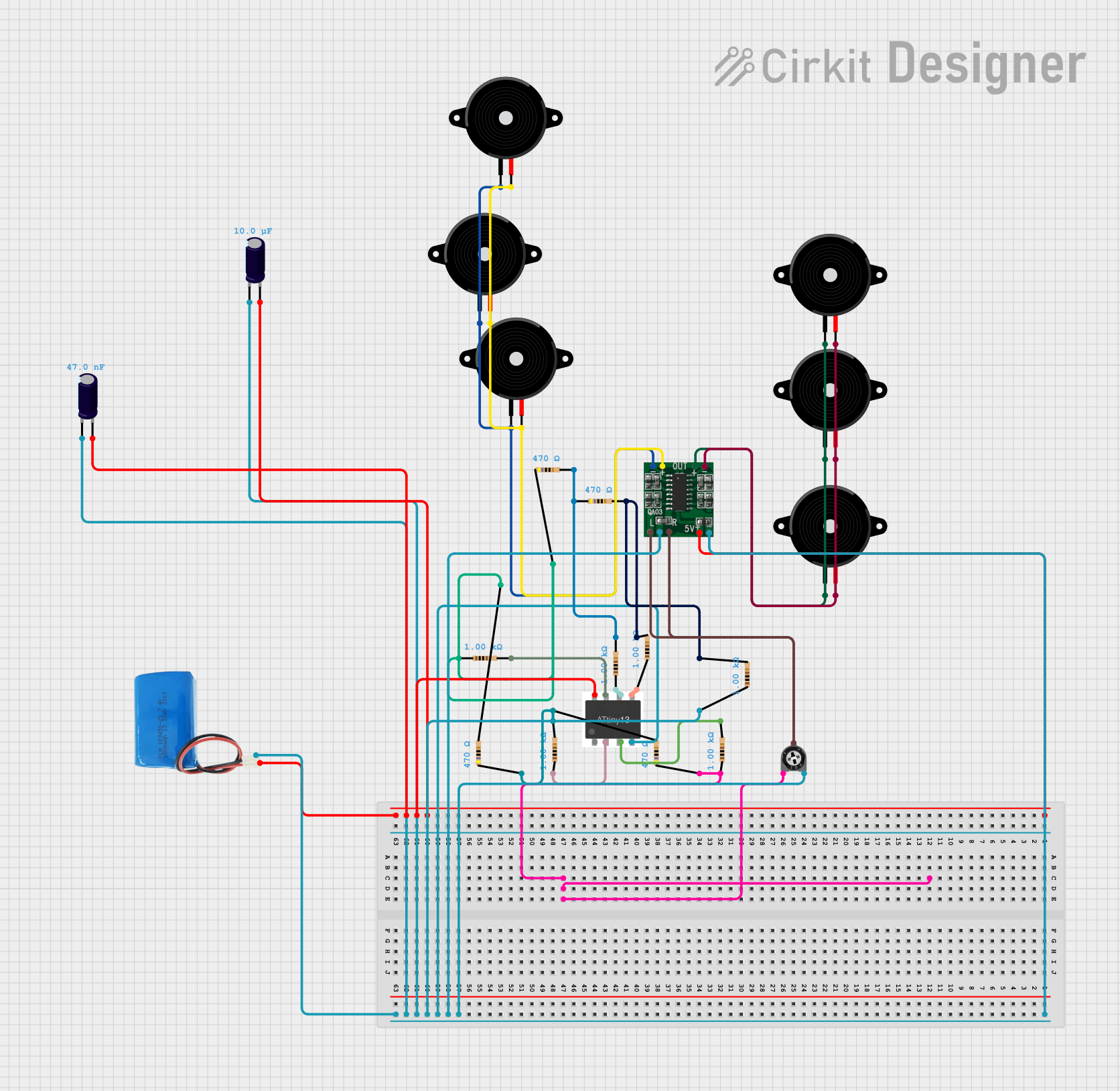
This circuit is an audio amplification system with multiple piezo speakers driven by a PAM8403 amplifier IC. It features an ATtiny microcontroller for potential audio control, powered by a 5V battery with capacitors for stabilization and a trimmer potentiometer for input level adjustment.
The following table outlines the key technical specifications of the LPA2172:
Parameter
Value
Supply Voltage (Vcc)
4.5V to 26V
Output Power
Up to 20W (high power mode)
Input Impedance
20 kΩ
Total Harmonic Distortion (THD)
< 0.1% (at 1kHz, 1W output)
Efficiency
> 85%
Operating Temperature
-40°C to +85°C
Package Type
DIP-16 or SOP-16
Pin Configuration and Descriptions
The LPA2172 is available in a 16-pin package. The pinout and descriptions are as follows:
Pin Number
Pin Name
Description
1
IN+
Non-inverting audio input
2
IN-
Inverting audio input
3
GND
Ground (common reference)
4
VCC
Positive power supply
5
OUT1
Output for Channel 1
6
OUT2
Output for Channel 2
7
NC
No connection
8
MUTE
Mute control input (active high)
9
STBY
Standby control input (active high)
10
GND
Ground (common reference)
11
VCC
Positive power supply
12
OUT3
Output for Channel 3
13
OUT4
Output for Channel 4
14
NC
No connection
15
IN+
Non-inverting audio input
16
IN-
Inverting audio input
Usage Instructions
How to Use the LPA2172 in a Circuit
Power Supply: Connect the VCC pins (4 and 11) to a stable DC power supply within the range of 4.5V to 26V. Ensure proper decoupling capacitors (e.g., 100µF and 0.1µF) are placed near the VCC pins to reduce noise.
Audio Input: Feed the audio signal to the IN+ and IN- pins. Use coupling capacitors (e.g., 1µF) to block DC components in the input signal.
Speaker Connection: Connect the speakers to the output pins (OUT1, OUT2, OUT3, OUT4). Ensure the speaker impedance matches the amplifier's specifications.
Mute and Standby: Use the MUTE and STBY pins to control the amplifier's operation. Pull these pins high to activate mute or standby modes, and pull them low to enable normal operation.
Heat Dissipation: If operating at high power, ensure proper heat dissipation by attaching a heatsink to the IC or using a PCB with good thermal management.
Important Considerations and Best Practices
Avoid Overloading: Ensure the connected speakers do not exceed the power rating of the amplifier to prevent damage.
Minimize Noise: Use shielded cables for audio input signals to reduce electromagnetic interference (EMI).
Thermal Management: Monitor the IC's temperature during operation. Use a heatsink or active cooling if necessary.
Power Supply Filtering: Use high-quality capacitors to filter the power supply and reduce ripple.
Example: Connecting the LPA2172 to an Arduino UNO
The LPA2172 can be used with an Arduino UNO to amplify audio signals. Below is an example of how to control the MUTE and STBY pins using the Arduino:
Circuit Connections
Connect the MUTE pin of the LPA2172 to Arduino digital pin 7.
Connect the STBY pin of the LPA2172 to Arduino digital pin 8.
Connect the audio input to the IN+ and IN- pins of the LPA2172.
Connect the speakers to the output pins (e.g., OUT1 and OUT2).
Arduino Code
// Define pin connections for MUTE and STBY
const int mutePin = 7;  // MUTE control pin
const int standbyPin = 8;  // Standby control pin

void setup() {
  // Set MUTE and STBY pins as outputs
  pinMode(mutePin, OUTPUT);
  pinMode(standbyPin, OUTPUT);

  // Initialize the amplifier in normal operation mode
  digitalWrite(mutePin, LOW);  // Disable mute
  digitalWrite(standbyPin, LOW);  // Disable standby
}

void loop() {
  // Example: Toggle mute mode every 5 seconds
  digitalWrite(mutePin, HIGH);  // Enable mute
  delay(5000);  // Wait for 5 seconds
  digitalWrite(mutePin, LOW);  // Disable mute
  delay(5000);  // Wait for 5 seconds
}
Troubleshooting and FAQs
Common Issues and Solutions
No Sound Output
Cause: Incorrect wiring or loose connections.
Solution: Double-check all connections, especially the audio input and speaker connections.
Distorted Audio
Cause: Overdriving the input signal or insufficient power supply.
Solution: Reduce the input signal amplitude and ensure the power supply meets the IC's requirements.
Overheating
Cause: High power operation without proper heat dissipation.
Solution: Attach a heatsink to the IC or improve PCB thermal design.
Amplifier Stuck in Mute or Standby Mode
Cause: MUTE or STBY pins are incorrectly configured.
Solution: Ensure the MUTE and STBY pins are pulled low for normal operation.
FAQs
Q1: Can the LPA2172 drive 4Ω speakers? A1: Yes, the LPA2172 can drive 4Ω speakers, but ensure the power supply and thermal management are adequate.
Q2: What is the maximum output power of the LPA2172? A2: The LPA2172 can deliver up to 20W of output power in high power mode, depending on the supply voltage and load impedance.
Q3: How do I reduce noise in the audio output? A3: Use proper grounding, shielded cables for input signals, and decoupling capacitors on the power supply lines.
Q4: Can I use the LPA2172 with a battery-powered system? A4: Yes, the LPA2172 is suitable for battery-powered systems as long as the supply voltage is within the 4.5V to 26V range.


 Open Project in Cirkit Designer