Cirkit Designer Logo
Cirkit Designer
Your all-in-one circuit design IDE
Home / 
Component Documentation

How to Use voltage regulator: Examples, Pinouts, and Specs

Image of voltage regulator
Cirkit Designer LogoDesign with voltage regulator in Cirkit Designer

Introduction

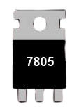
The LM7805 is a fixed-output voltage regulator manufactured by CDIL (Continental Device India Ltd). It is designed to provide a stable 5V DC output, making it ideal for powering sensitive electronic components and circuits. The LM7805 is part of the 78xx series of voltage regulators, which are widely used in power supply designs due to their reliability and ease of use.

Explore Projects Built with voltage regulator

Use Cirkit Designer to design, explore, and prototype these projects online. Some projects support real-time simulation. Click "Open Project" to start designing instantly!
LM317 Voltage Regulator Circuit for Adjustable Power Supply with Transformer and Diodes
Image of 12V BULB LIGHT DIMMER CIRCUIT: A project utilizing voltage regulator in a practical application
This circuit is a regulated power supply that converts AC voltage to a stable DC voltage. It uses a transformer to step down the AC voltage, diodes for rectification, an electrolytic capacitor for smoothing, and an LM317 voltage regulator to provide a stable output voltage, which is adjustable via a potentiometer. The output powers a bulb.
Cirkit Designer LogoOpen Project in Cirkit Designer
LD1117 Voltage Regulator Circuit with Input and Output Capacitors
Image of regulator: A project utilizing voltage regulator in a practical application
This circuit is designed to provide a stable output voltage from an input voltage source. It uses an LD1117 voltage regulator in conjunction with an electrolytic capacitor on the input side and a tantalum capacitor on the output side to filter noise and stabilize the voltage. The common ground ensures a reference point for all components.
Cirkit Designer LogoOpen Project in Cirkit Designer
Battery-Powered LED Control Circuit with Potentiometer and Transistors
Image of STROBE LIGHTS: A project utilizing voltage regulator in a practical application
This circuit is a regulated power supply with a 12V battery input, a 7805 voltage regulator providing a 5V output, and a potentiometer for adjustable voltage control. It includes transistors and resistors for current regulation and an LED indicator to show the operational status.
Cirkit Designer LogoOpen Project in Cirkit Designer
LM317 Voltage Regulator Circuit with Bridge Rectifier for Stable DC Output
Image of voltage regualator using LM317 IC: A project utilizing voltage regulator in a practical application
This circuit converts 220V AC to a regulated DC voltage using a bridge rectifier, smoothing capacitors, and an LM317 voltage regulator. The output voltage can be adjusted using a potentiometer connected to the LM317's adjustment pin.
Cirkit Designer LogoOpen Project in Cirkit Designer

Explore Projects Built with voltage regulator

Use Cirkit Designer to design, explore, and prototype these projects online. Some projects support real-time simulation. Click "Open Project" to start designing instantly!
Image of 12V BULB LIGHT DIMMER CIRCUIT: A project utilizing voltage regulator in a practical application
LM317 Voltage Regulator Circuit for Adjustable Power Supply with Transformer and Diodes
This circuit is a regulated power supply that converts AC voltage to a stable DC voltage. It uses a transformer to step down the AC voltage, diodes for rectification, an electrolytic capacitor for smoothing, and an LM317 voltage regulator to provide a stable output voltage, which is adjustable via a potentiometer. The output powers a bulb.
Cirkit Designer LogoOpen Project in Cirkit Designer
Image of regulator: A project utilizing voltage regulator in a practical application
LD1117 Voltage Regulator Circuit with Input and Output Capacitors
This circuit is designed to provide a stable output voltage from an input voltage source. It uses an LD1117 voltage regulator in conjunction with an electrolytic capacitor on the input side and a tantalum capacitor on the output side to filter noise and stabilize the voltage. The common ground ensures a reference point for all components.
Cirkit Designer LogoOpen Project in Cirkit Designer
Image of STROBE LIGHTS: A project utilizing voltage regulator in a practical application
Battery-Powered LED Control Circuit with Potentiometer and Transistors
This circuit is a regulated power supply with a 12V battery input, a 7805 voltage regulator providing a 5V output, and a potentiometer for adjustable voltage control. It includes transistors and resistors for current regulation and an LED indicator to show the operational status.
Cirkit Designer LogoOpen Project in Cirkit Designer
Image of voltage regualator using LM317 IC: A project utilizing voltage regulator in a practical application
LM317 Voltage Regulator Circuit with Bridge Rectifier for Stable DC Output
This circuit converts 220V AC to a regulated DC voltage using a bridge rectifier, smoothing capacitors, and an LM317 voltage regulator. The output voltage can be adjusted using a potentiometer connected to the LM317's adjustment pin.
Cirkit Designer LogoOpen Project in Cirkit Designer

Common Applications and Use Cases

  • Power supply circuits for microcontrollers, sensors, and other electronic devices
  • Voltage regulation in battery-powered systems
  • Protection of sensitive components from voltage fluctuations
  • DIY electronics projects and prototyping

Technical Specifications

The LM7805 is a robust and versatile component with the following key specifications:

Parameter Value
Output Voltage 5V DC
Input Voltage Range 7V to 35V
Maximum Output Current 1.5A
Dropout Voltage 2V (typical)
Operating Temperature 0°C to +125°C
Package Type TO-220
Thermal Shutdown Yes
Short-Circuit Protection Yes

Pin Configuration and Descriptions

The LM7805 has three pins, as shown in the table below:

Pin Number Pin Name Description
1 Input Connects to the unregulated input voltage source
2 Ground Common ground for input and output
3 Output Provides the regulated 5V output

Usage Instructions

How to Use the LM7805 in a Circuit

  1. Input Voltage: Connect a DC voltage source (7V to 35V) to the Input pin. Ensure the input voltage is at least 2V higher than the desired 5V output to account for the dropout voltage.
  2. Output Voltage: Connect the Output pin to the load or circuit requiring a stable 5V supply.
  3. Ground Connection: Connect the Ground pin to the common ground of the circuit.
  4. Capacitors: Add decoupling capacitors to improve stability and reduce noise:
    • Place a 0.33µF capacitor between the
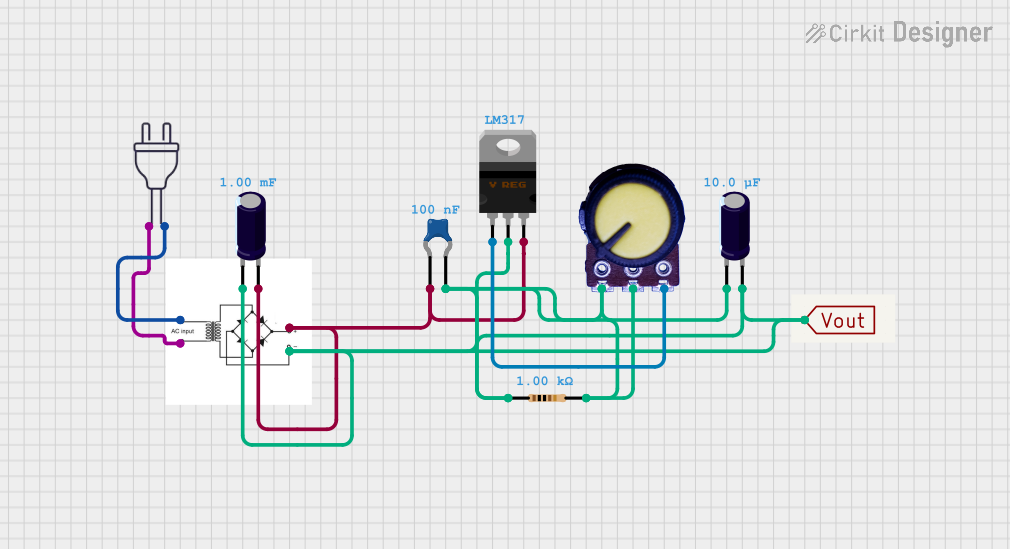
 Input pin and ground.
    • Place a 0.1µF capacitor between the Output pin and ground.

Circuit Diagram

Below is a simple circuit diagram for using the LM7805:

   Input Voltage (7V-35V)
          |
          |
         [C1]  0.33µF
          |
          |-----> Pin 1 (Input)
          |
         GND
          |
          |-----> Pin 2 (Ground)
          |
          |
         [C2]  0.1µF
          |
          |-----> Pin 3 (Output) -----> Regulated 5V Output

Arduino UNO Example

The LM7805 can be used to power an Arduino UNO by providing a stable 5V supply. Below is an example of how to connect the LM7805 to an Arduino UNO:

  1. Connect the Output pin of the LM7805 to the 5V pin of the Arduino UNO.
  2. Connect the Ground pin of the LM7805 to the GND pin of the Arduino UNO.
  3. Connect the Input pin of the LM7805 to a DC voltage source (e.g., 9V battery or adapter).

Important Considerations and Best Practices

  • Heat Dissipation: The LM7805 can generate heat during operation, especially at high input voltages or currents. Use a heatsink to prevent overheating.
  • Input Voltage Range: Ensure the input voltage is within the specified range (7V to 35V) to avoid damage to the regulator.
  • Load Current: Do not exceed the maximum output current of 1.5A to ensure reliable operation.
  • Bypass Capacitors: Always use the recommended capacitors to improve stability and reduce noise.

Troubleshooting and FAQs

Common Issues and Solutions

  1. No Output Voltage

    • Cause: Input voltage is too low.
    • Solution: Ensure the input voltage is at least 7V.
  2. Overheating

    • Cause: Excessive input voltage or current.
    • Solution: Use a heatsink or reduce the input voltage/current.
  3. Output Voltage Fluctuations

    • Cause: Missing or incorrect decoupling capacitors.
    • Solution: Add the recommended capacitors (0.33µF on input, 0.1µF on output).
  4. Short Circuit

    • Cause: Output is shorted to ground.
    • Solution: Disconnect the load, check for shorts, and reconnect after resolving the issue.

FAQs

Q1: Can I use the LM7805 to power a 3.3V device?
A1: No, the LM7805 provides a fixed 5V output. To power a 3.3V device, use a voltage regulator designed for 3.3V output, such as the LM7833.

Q2: What happens if the input voltage exceeds 35V?
A2: Exceeding the maximum input voltage can damage the LM7805. Always ensure the input voltage is within the specified range.

Q3: Can I use the LM7805 without capacitors?
A3: While the LM7805 can function without capacitors, it is highly recommended to use them to improve stability and reduce noise.

Q4: Is the LM7805 suitable for battery-powered applications?
A4: Yes, but ensure the battery voltage is within the input voltage range and consider the dropout voltage when designing the circuit.