
How to Use Atlas Scientific 4:1 Serial Port Connector: Examples, Pinouts, and Specs
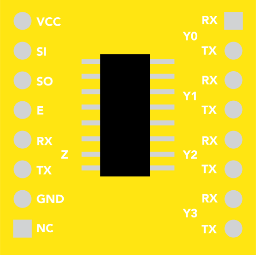
 Design with Atlas Scientific 4:1 Serial Port Connector in Cirkit Designer
Introduction
The Atlas Scientific 4:1 Serial Port Connector is a versatile multi-port device designed to connect up to four serial devices to a single serial port. This component simplifies communication and data transfer in electronic systems by enabling multiple devices to share a single UART (Universal Asynchronous Receiver-Transmitter) interface. It is particularly useful in applications where multiple sensors or modules need to communicate with a microcontroller or computer.
Explore Projects Built with Atlas Scientific 4:1 Serial Port Connector
 Open Project in Cirkit Designer
 Open Project in Cirkit Designer
 Open Project in Cirkit Designer
 Open Project in Cirkit Designer
Explore Projects Built with Atlas Scientific 4:1 Serial Port Connector
Open Project in Cirkit DesignerOpen Project in Cirkit DesignerOpen Project in Cirkit DesignerOpen Project in Cirkit DesignerCommon Applications and Use Cases
- Environmental monitoring systems with multiple sensors
- Data acquisition systems
- Laboratory automation
- IoT (Internet of Things) projects requiring multiple serial devices
- Robotics and industrial control systems
Technical Specifications
The Atlas Scientific 4:1 Serial Port Connector is designed to work seamlessly with a wide range of serial devices. Below are its key technical details:
Key Technical Details
| Parameter | Specification |
|---|---|
| Operating Voltage | 3.3V to 5V |
| Communication Protocol | UART (Serial) |
| Baud Rate Support | 300 to 115200 bps |
| Number of Serial Ports | 4 input ports, 1 output port |
| Dimensions | 42mm x 20mm x 5mm |
| Operating Temperature | -40°C to 85°C |
| Current Consumption | ~5mA |
Pin Configuration and Descriptions
The Atlas Scientific 4:1 Serial Port Connector has a straightforward pin layout. Below is the pin configuration:
Input Ports (Serial Devices)
| Pin Name | Description |
|---|---|
| RX1 | Receive pin for Serial Device 1 |
| TX1 | Transmit pin for Serial Device 1 |
| RX2 | Receive pin for Serial Device 2 |
| TX2 | Transmit pin for Serial Device 2 |
| RX3 | Receive pin for Serial Device 3 |
| TX3 | Transmit pin for Serial Device 3 |
| RX4 | Receive pin for Serial Device 4 |
| TX4 | Transmit pin for Serial Device 4 |
Output Port (To Microcontroller/Host)
| Pin Name | Description |
|---|---|
| RX | Receive pin for the microcontroller/host device |
| TX | Transmit pin for the microcontroller/host device |
Power and Control Pins
| Pin Name | Description |
|---|---|
| VCC | Power supply input (3.3V to 5V) |
| GND | Ground |
| SEL1 | Selection pin for Serial Device 1 |
| SEL2 | Selection pin for Serial Device 2 |
| SEL3 | Selection pin for Serial Device 3 |
| SEL4 | Selection pin for Serial Device 4 |
Usage Instructions
How to Use the Component in a Circuit
- Power the Connector: Connect the VCC pin to a 3.3V or 5V power source and the GND pin to ground.
- Connect Serial Devices: Attach up to four serial devices to the RX and TX pins of the input ports (RX1/TX1, RX2/TX2, etc.).
- Connect to Microcontroller: Connect the RX and TX pins of the output port to the corresponding UART pins on your microcontroller or host device.
- Select Active Device: Use the SEL1, SEL2, SEL3, and SEL4 pins to select which serial device is active. Only one device can communicate with the microcontroller at a time.
Important Considerations and Best Practices
- Voltage Compatibility: Ensure that all connected devices operate at the same voltage level (3.3V or 5V).
- Device Selection: Use GPIO pins on your microcontroller to control the SEL pins. Set the corresponding SEL pin HIGH to activate a device, and keep all other SEL pins LOW.
- Baud Rate Matching: Ensure that the baud rate of the microcontroller matches the baud rate of the selected serial device.
- Avoid Signal Interference: Keep the wiring between the connector and devices as short as possible to minimize noise and signal degradation.
Example Code for Arduino UNO
Below is an example of how to use the Atlas Scientific 4:1 Serial Port Connector with an Arduino UNO to communicate with multiple serial devices:
// Example code for using the Atlas Scientific 4:1 Serial Port Connector
// with an Arduino UNO. This code demonstrates how to switch between
// multiple serial devices and read data from them.

#define SEL1 2  // GPIO pin connected to SEL1
#define SEL2 3  // GPIO pin connected to SEL2
#define SEL3 4  // GPIO pin connected to SEL3
#define SEL4 5  // GPIO pin connected to SEL4

void setup() {
  // Initialize serial communication
  Serial.begin(9600);  // Communication with the computer
  Serial1.begin(9600); // Communication with the serial devices

  // Configure SEL pins as outputs
  pinMode(SEL1, OUTPUT);
  pinMode(SEL2, OUTPUT);
  pinMode(SEL3, OUTPUT);
  pinMode(SEL4, OUTPUT);

  // Set all SEL pins LOW initially
  digitalWrite(SEL1, LOW);
  digitalWrite(SEL2, LOW);
  digitalWrite(SEL3, LOW);
  digitalWrite(SEL4, LOW);
}

void loop() {
  // Example: Read data from Serial Device 1
  selectDevice(1);
  if (Serial1.available()) {
    String data = Serial1.readString();
    Serial.println("Data from Device 1: " + data);
  }

  // Example: Read data from Serial Device 2
  selectDevice(2);
  if (Serial1.available()) {
    String data = Serial1.readString();
    Serial.println("Data from Device 2: " + data);
  }

  delay(1000); // Wait 1 second before switching devices
}

// Function to select a serial device
void selectDevice(int device) {
  // Set all SEL pins LOW
  digitalWrite(SEL1, LOW);
  digitalWrite(SEL2, LOW);
  digitalWrite(SEL3, LOW);
  digitalWrite(SEL4, LOW);

  // Set the corresponding SEL pin HIGH
  switch (device) {
    case 1:
      digitalWrite(SEL1, HIGH);
      break;
    case 2:
      digitalWrite(SEL2, HIGH);
      break;
    case 3:
      digitalWrite(SEL3, HIGH);
      break;
    case 4:
      digitalWrite(SEL4, HIGH);
      break;
    default:
      Serial.println("Invalid device selection");
  }
}
Troubleshooting and FAQs
Common Issues and Solutions
No Communication with Serial Devices
- Cause: Incorrect SEL pin configuration.
- Solution: Verify that the correct SEL pin is set HIGH and all others are LOW.
Data Corruption or Noise
- Cause: Long or poor-quality wiring.
- Solution: Use shorter, shielded cables to reduce noise and signal degradation.
Devices Not Responding
- Cause: Mismatched baud rates.
- Solution: Ensure that the baud rate of the microcontroller matches the baud rate of the selected serial device.
Power Issues
- Cause: Insufficient power supply.
- Solution: Ensure that the power source can supply adequate current for all connected devices.
FAQs
Q: Can I use this connector with I2C or SPI devices?
A: No, the Atlas Scientific 4:1 Serial Port Connector is designed specifically for UART (serial) communication.
Q: Can multiple devices communicate simultaneously?
A: No, only one device can be active at a time. Use the SEL pins to switch between devices.
Q: What happens if multiple SEL pins are set HIGH?
A: This may cause communication conflicts or undefined behavior. Ensure that only one SEL pin is HIGH at any given time.