How to Use Mosfet Module: Examples, Pinouts, and Specs
Introduction
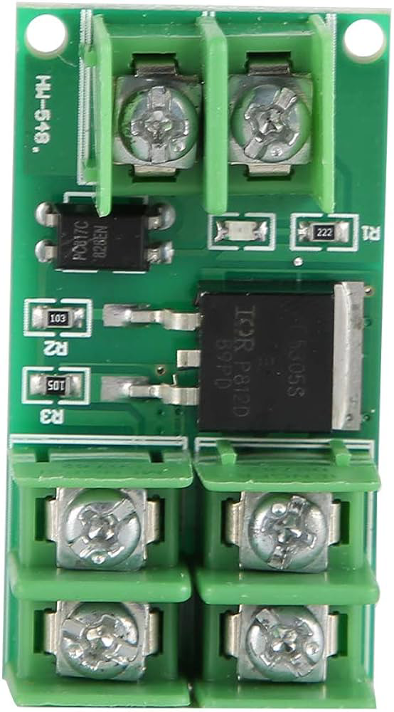
A MOSFET (Metal-Oxide-Semiconductor Field-Effect Transistor) module is a versatile electronic component designed for controlling high power and high voltage applications. It functions as a switch or amplifier in electronic circuits, enabling efficient management of electrical power. MOSFET modules are widely used in applications such as motor control, LED dimming, power supplies, and audio amplifiers. Their ability to handle high currents with minimal heat generation makes them an essential component in modern electronics.
Explore Projects Built with Mosfet Module
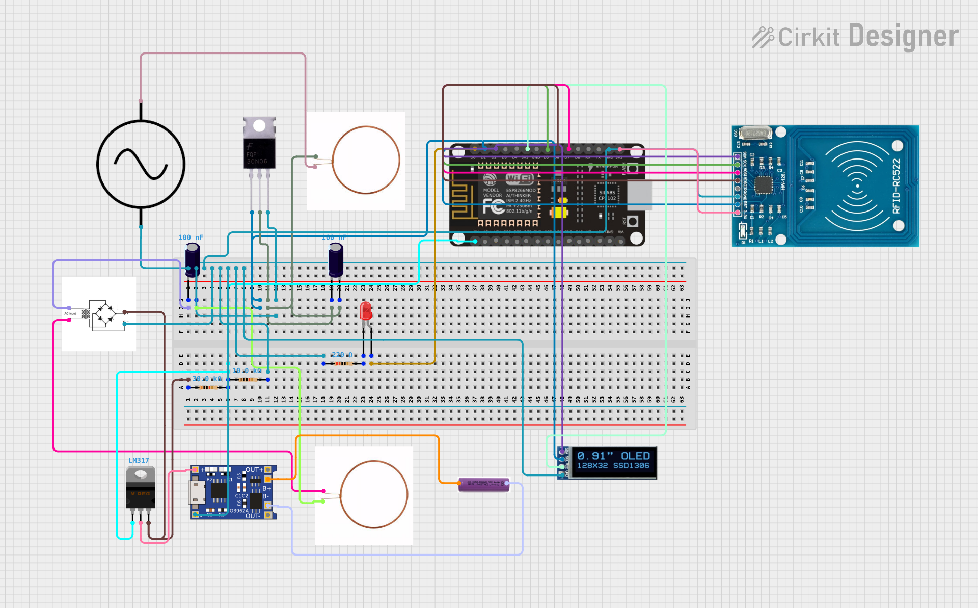
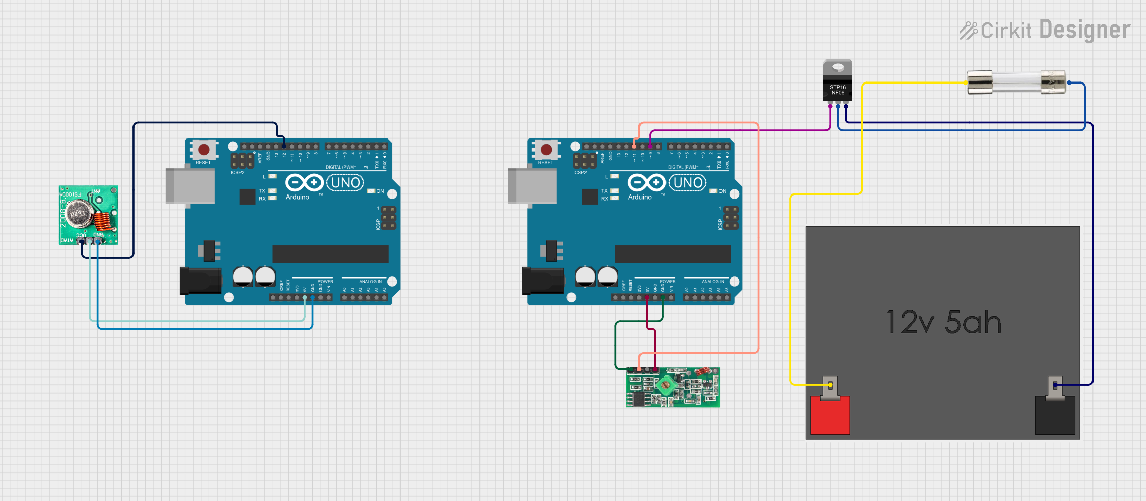

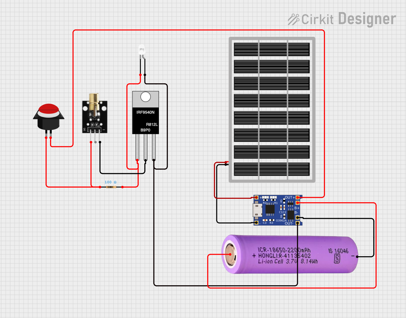
Explore Projects Built with Mosfet Module
Technical Specifications
Below are the key technical details and pin configurations for a typical MOSFET module:
Key Technical Details
- Operating Voltage: 5V to 24V (varies by module)
- Maximum Current: Up to 30A (check specific module rating)
- Control Signal Voltage: 3.3V or 5V logic level compatible
- On-Resistance (RDS(on)): Typically < 0.1Ω
- Switching Speed: High-speed switching capability
- Thermal Management: Integrated heat sink (on some modules)
- Protection Features: May include overcurrent, overvoltage, or thermal protection
Pin Configuration and Descriptions
The pin configuration of a typical MOSFET module is as follows:
| Pin Name | Description |
|---|---|
| VCC | Power supply input for the module (e.g., 5V or 12V). |
| GND | Ground connection for the module. |
| IN | Control signal input (logic level, e.g., from a microcontroller like Arduino). |
| OUT+ | Positive output terminal for the load. |
| OUT- | Negative output terminal for the load. |
Note: The exact pin configuration may vary depending on the specific MOSFET module. Always refer to the datasheet or manufacturer documentation for your module.
Usage Instructions
How to Use the MOSFET Module in a Circuit
- Power Supply: Connect the VCC pin to the appropriate power supply voltage (e.g., 12V) and the GND pin to the ground of your circuit.
- Control Signal: Connect the IN pin to a digital output pin of a microcontroller (e.g., Arduino UNO). Ensure the control signal voltage matches the module's logic level requirements (3.3V or 5V).
- Load Connection: Connect the load (e.g., motor, LED strip) between the OUT+ and OUT- terminals.
- Enable Control: Use the microcontroller to send a HIGH or LOW signal to the IN pin to turn the MOSFET on or off, respectively.
Important Considerations and Best Practices
- Heat Dissipation: If the module is handling high currents, ensure proper heat dissipation using a heat sink or active cooling.
- Flyback Diode: For inductive loads (e.g., motors, relays), use a flyback diode across the load to protect the MOSFET from voltage spikes.
- Logic Level Compatibility: Verify that the control signal voltage from your microcontroller matches the module's input requirements.
- Current Rating: Ensure the load current does not exceed the module's maximum current rating.
Example: Using a MOSFET Module with Arduino UNO
Below is an example of controlling an LED strip using a MOSFET module and Arduino UNO:
// Define the control pin connected to the MOSFET module
const int mosfetControlPin = 9;

void setup() {
  // Set the MOSFET control pin as an output
  pinMode(mosfetControlPin, OUTPUT);
}

void loop() {
  // Turn the MOSFET on (LED strip ON)
  digitalWrite(mosfetControlPin, HIGH);
  delay(1000); // Keep the LED strip ON for 1 second

  // Turn the MOSFET off (LED strip OFF)
  digitalWrite(mosfetControlPin, LOW);
  delay(1000); // Keep the LED strip OFF for 1 second
}
Note: Ensure the Arduino GND is connected to the MOSFET module's GND for proper operation.
Troubleshooting and FAQs
Common Issues and Solutions
MOSFET Not Switching Properly
- Cause: Control signal voltage is too low.
- Solution: Verify that the control signal voltage matches the module's input requirements (e.g., 5V for a 5V logic-level MOSFET).
Excessive Heat Generation
- Cause: High current through the MOSFET or insufficient heat dissipation.
- Solution: Use a heat sink or active cooling. Ensure the load current is within the module's rated capacity.
Load Not Turning On
- Cause: Incorrect wiring or insufficient power supply voltage.
- Solution: Double-check all connections and ensure the power supply voltage is adequate for the load.
Voltage Spikes Damaging the MOSFET
- Cause: Inductive load without a flyback diode.
- Solution: Add a flyback diode across the load to suppress voltage spikes.
FAQs
Q: Can I use a MOSFET module with a 3.3V microcontroller?
A: Yes, but ensure the module is compatible with 3.3V logic levels. Some modules require 5V signals.Q: How do I know if my MOSFET module needs a heat sink?
A: If the module becomes excessively hot during operation, a heat sink or active cooling is recommended.Q: Can I use a MOSFET module to control an AC load?
A: No, standard MOSFET modules are designed for DC loads. Use a TRIAC or relay module for AC loads.Q: What is the maximum PWM frequency for a MOSFET module?
A: This depends on the specific MOSFET used in the module. Most modules can handle PWM frequencies in the range of tens to hundreds of kHz. Check the datasheet for details.