How to Use ESP-WROOM-32 (Breadboard): Examples, Pinouts, and Specs
Introduction
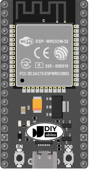
The ESP-WROOM-32 is a versatile Wi-Fi and Bluetooth module developed by Espressif Systems. It is based on the powerful ESP32 chip, which integrates a dual-core processor, wireless connectivity, and a variety of peripherals. The breadboard-friendly design of the ESP-WROOM-32 makes it an excellent choice for prototyping and integrating into Internet of Things (IoT) projects.
Explore Projects Built with ESP-WROOM-32 (Breadboard)
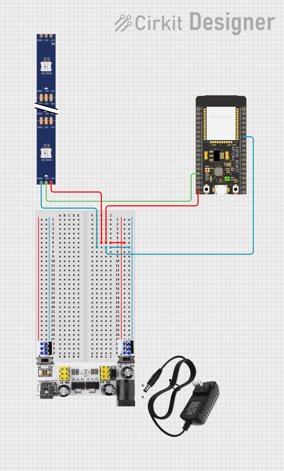

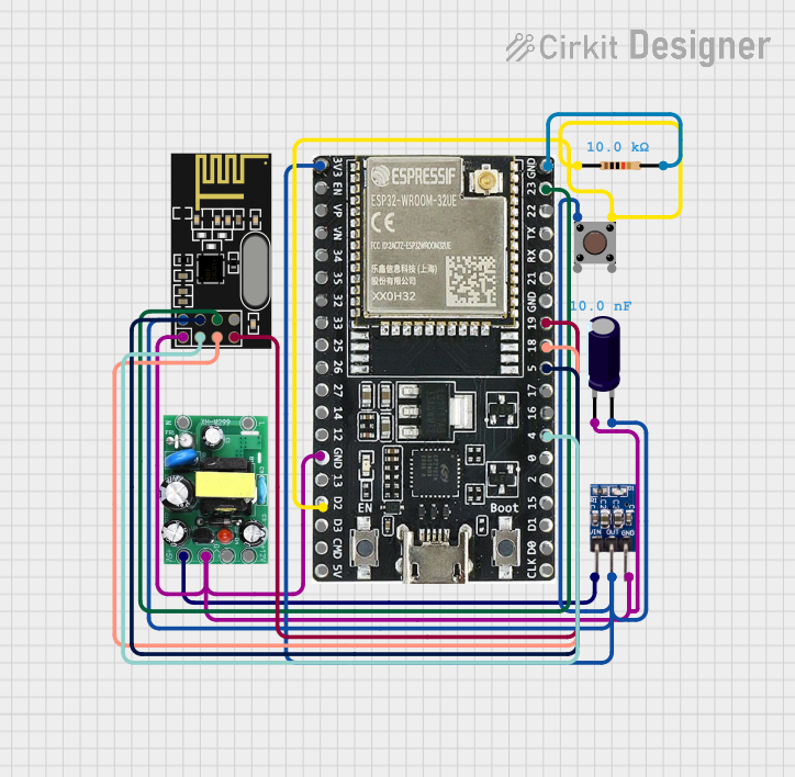

Explore Projects Built with ESP-WROOM-32 (Breadboard)
Common Applications and Use Cases
- IoT devices and smart home automation
- Wireless sensor networks
- Wearable electronics
- Industrial automation
- Robotics and drones
- Real-time data monitoring and logging
Technical Specifications
The ESP-WROOM-32 module is packed with features that make it suitable for a wide range of applications. Below are its key technical specifications:
| Parameter | Specification |
|---|---|
| Microcontroller | ESP32 (dual-core Xtensa® 32-bit LX6 processor) |
| Clock Speed | Up to 240 MHz |
| Flash Memory | 4 MB (default) |
| SRAM | 520 KB |
| Wireless Connectivity | Wi-Fi 802.11 b/g/n (2.4 GHz), Bluetooth v4.2 BR/EDR and BLE |
| Operating Voltage | 3.3 V |
| Input Voltage Range | 3.0 V to 3.6 V |
| GPIO Pins | 34 (multiplexed with other functions) |
| ADC Channels | 18 (12-bit resolution) |
| DAC Channels | 2 (8-bit resolution) |
| Communication Interfaces | UART, SPI, I2C, I2S, CAN, PWM |
| Power Consumption | Ultra-low power consumption in deep sleep mode (~10 µA) |
| Dimensions | 25.5 mm x 18 mm |
| Operating Temperature | -40°C to +85°C |
Pin Configuration and Descriptions
The ESP-WROOM-32 module has a total of 38 pins. Below is a table describing the most commonly used pins:
| Pin Name | Pin Number | Function |
|---|---|---|
| GND | Multiple | Ground |
| 3V3 | 1 | 3.3 V power supply |
| EN | 3 | Enable pin (active high, resets the chip when pulled low) |
| GPIO0 | 25 | Used for boot mode selection (must be pulled low for flashing) |
| GPIO2 | 26 | General-purpose I/O pin |
| GPIO16 | 8 | General-purpose I/O pin |
| GPIO17 | 9 | General-purpose I/O pin |
| TXD0 | 21 | UART0 Transmit |
| RXD0 | 22 | UART0 Receive |
| ADC1_CH0 | 36 | Analog-to-Digital Converter channel 0 |
| DAC1 | 25 | Digital-to-Analog Converter channel 1 |
| IO34 | 34 | Input-only GPIO |
Note: Some pins are multiplexed with other functions, such as ADC, DAC, or touch sensing. Refer to the ESP32 datasheet for detailed pin mappings.
Usage Instructions
How to Use the ESP-WROOM-32 in a Circuit
- Powering the Module:
- Connect the 3V3 pin to a 3.3 V power source.
- Ensure the power supply can provide sufficient current (at least 500 mA) for stable operation.
- Connecting to a Breadboard:
- Insert the module into a breadboard. The breadboard-friendly design ensures easy prototyping.
- Programming the Module:
- Use a USB-to-Serial adapter (e.g., FTDI or CP2102) to connect the module to your computer.
- Connect the TXD0 pin to the RX pin of the adapter and the RXD0 pin to the TX pin of the adapter.
- Pull the GPIO0 pin low to enter flashing mode.
- Flashing Firmware:
- Use the Espressif ESP-IDF or the Arduino IDE to upload code to the module.
- Select the appropriate board (e.g., "ESP32 Dev Module") in the IDE.
Important Considerations and Best Practices
- Voltage Levels: The ESP-WROOM-32 operates at 3.3 V. Avoid applying 5 V to any GPIO pin to prevent damage.
- Boot Mode: Ensure the GPIO0 pin is pulled low during flashing and released afterward.
- Antenna Placement: Avoid placing metal objects near the onboard antenna to ensure optimal wireless performance.
- Power Supply: Use a stable power source to prevent unexpected resets or instability.
Example: Connecting to an Arduino UNO
The ESP-WROOM-32 can communicate with an Arduino UNO via UART. Below is an example of how to send data from the Arduino to the ESP-WROOM-32:
Arduino Code Example
// Example: Sending data from Arduino UNO to ESP-WROOM-32 via UART

void setup() {
  Serial.begin(9600); // Initialize Arduino's serial communication
  Serial.println("Arduino is ready to communicate with ESP-WROOM-32");
}

void loop() {
  // Send a message to the ESP-WROOM-32 every 2 seconds
  Serial.println("Hello from Arduino!");
  delay(2000);
}
ESP-WROOM-32 Code Example (Arduino IDE)
// Example: Receiving data from Arduino UNO on ESP-WROOM-32

void setup() {
  Serial.begin(9600); // Initialize ESP-WROOM-32's serial communication
  Serial.println("ESP-WROOM-32 is ready to receive data");
}

void loop() {
  // Check if data is available from Arduino
  if (Serial.available()) {
    String data = Serial.readString(); // Read the incoming data
    Serial.print("Received: ");
    Serial.println(data); // Print the received data
  }
}
Note: Ensure the Arduino's TX pin is connected to the ESP-WROOM-32's RXD0 pin, and the RX pin is connected to the TXD0 pin.
Troubleshooting and FAQs
Common Issues and Solutions
Module Not Responding:
- Ensure the module is powered correctly (3.3 V, sufficient current).
- Check the connections to the USB-to-Serial adapter.
- Verify that the GPIO0 pin is pulled low during flashing.
Wi-Fi Connection Fails:
- Ensure the correct SSID and password are used in the code.
- Check for interference or weak signal strength near the module.
Random Resets:
- Verify the power supply is stable and capable of providing at least 500 mA.
- Add a capacitor (e.g., 10 µF) across the power supply pins to filter noise.
Serial Communication Issues:
- Ensure the baud rate in the code matches the baud rate of the Serial Monitor.
- Double-check the TX and RX connections between the ESP-WROOM-32 and the other device.
FAQs
Q: Can the ESP-WROOM-32 operate on 5 V?
A: No, the module operates at 3.3 V. Use a level shifter if interfacing with 5 V devices.
Q: How do I reset the module?
A: Pull the EN pin low momentarily to reset the module.
Q: Can I use the ESP-WROOM-32 for Bluetooth communication?
A: Yes, the module supports Bluetooth Classic and BLE (Bluetooth Low Energy).
Q: What is the maximum range of the Wi-Fi connection?
A: The range depends on the environment but typically extends up to 100 meters in open space.
For more detailed information, refer to the official Espressif ESP-WROOM-32 datasheet.