Cirkit Designer
Your all-in-one circuit design IDE
Home /
Component Documentation
How to Use Adafruit Adalogger FeatherWing: Examples, Pinouts, and Specs
Introduction
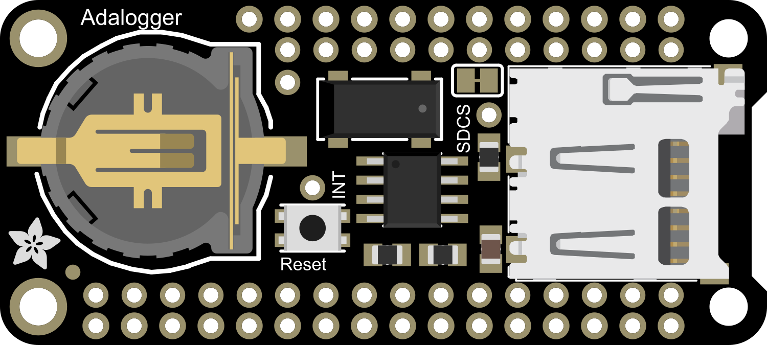
The Adafruit Adalogger FeatherWing is a versatile add-on board designed for the Adafruit Feather series of microcontroller boards. It features an SD card slot for data logging, a real-time clock (RTC) for precise timekeeping, and compatibility with various sensors for environmental monitoring. This compact and efficient board is ideal for projects requiring data storage, timestamping, and sensor integration.
Explore Projects Built with Adafruit Adalogger FeatherWing
Solar-Powered Environmental Data Logger with Adafruit Feather M0 Express

This circuit is designed for environmental data collection and logging, utilizing an Adafruit Feather M0 Express microcontroller as the central processing unit. It interfaces with a BME280 sensor for atmospheric temperature, humidity, and pressure measurements, an SGP30 sensor for monitoring air quality (eCO2 and TVOC), and a STEMMA soil sensor for detecting soil moisture and temperature. The system is powered by a solar panel and a 3.7v LiPo battery, managed by an Adafruit BQ24074 Solar-DC-USB Lipo Charger, and provides easy access to the microcontroller's connections through an Adafruit Terminal Breakout FeatherWing.
Multi-Sensor Health Monitoring System with Adafruit Feather M0 Adalogger
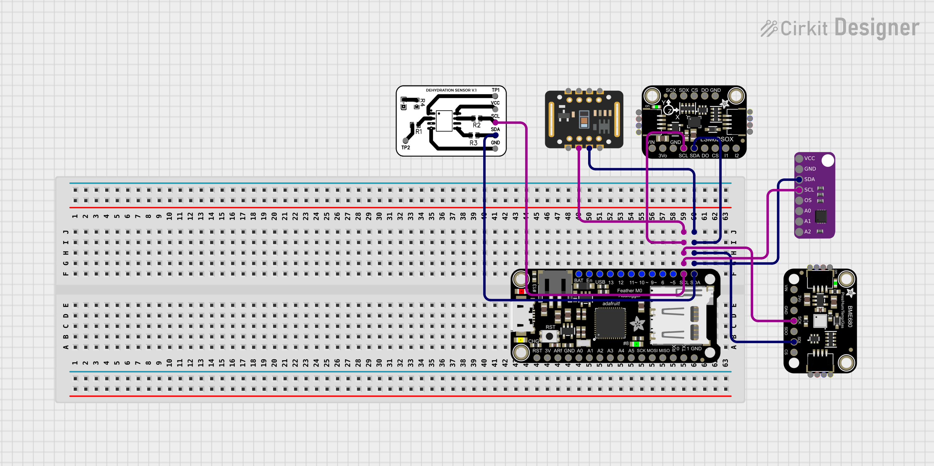
This circuit is designed to interface multiple sensors with an Adafruit Feather M0 Adalogger microcontroller for data logging purposes. The sensors include a MAX30205 temperature sensor, a body dehydration sensor, a MAX30102 pulse oximeter, an Adafruit LSM6DSOX 6-axis accelerometer and gyroscope, and an Adafruit BME680 environmental sensor. All sensors are connected to the microcontroller via an I2C bus, sharing the SDA and SCL lines for communication.
ESP32-Based Vibration Feedback System with Quad Alphanumeric Display and ADXL343 Accelerometer
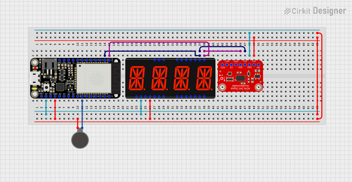
This circuit features an Adafruit HUZZAH32 ESP32 Feather board as the central microcontroller, which is connected to an Adafruit Quad AlphaNumeric Featherwing display and an Adafruit ADXL343 accelerometer via I2C communication (SCL and SDA lines). The ESP32 controls a vibration motor connected to one of its GPIO pins (A5_IO4) and shares a common power supply (3.3V) and ground (GND) with the other components. The purpose of this circuit is likely to read acceleration data, display information on the alphanumeric display, and provide haptic feedback through the vibration motor.
Arduino UNO and OLED FeatherWing Display: Battery-Powered Hello World Project
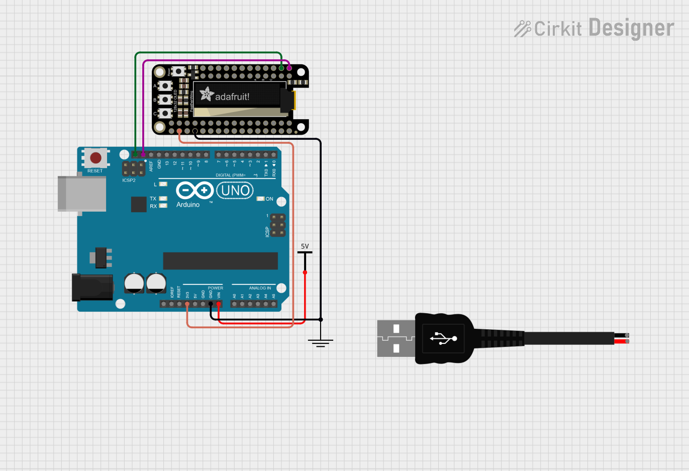
This circuit consists of an Arduino UNO connected to an Adafruit OLED FeatherWing display via I2C communication (SDA and SCL lines). The Arduino is powered through a Vcc source and provides 3.3V and GND connections to the OLED display. The Arduino runs a program to display 'Hello, World!' on the OLED screen.
Explore Projects Built with Adafruit Adalogger FeatherWing
Solar-Powered Environmental Data Logger with Adafruit Feather M0 Express
This circuit is designed for environmental data collection and logging, utilizing an Adafruit Feather M0 Express microcontroller as the central processing unit. It interfaces with a BME280 sensor for atmospheric temperature, humidity, and pressure measurements, an SGP30 sensor for monitoring air quality (eCO2 and TVOC), and a STEMMA soil sensor for detecting soil moisture and temperature. The system is powered by a solar panel and a 3.7v LiPo battery, managed by an Adafruit BQ24074 Solar-DC-USB Lipo Charger, and provides easy access to the microcontroller's connections through an Adafruit Terminal Breakout FeatherWing.
Multi-Sensor Health Monitoring System with Adafruit Feather M0 Adalogger
This circuit is designed to interface multiple sensors with an Adafruit Feather M0 Adalogger microcontroller for data logging purposes. The sensors include a MAX30205 temperature sensor, a body dehydration sensor, a MAX30102 pulse oximeter, an Adafruit LSM6DSOX 6-axis accelerometer and gyroscope, and an Adafruit BME680 environmental sensor. All sensors are connected to the microcontroller via an I2C bus, sharing the SDA and SCL lines for communication.
ESP32-Based Vibration Feedback System with Quad Alphanumeric Display and ADXL343 Accelerometer
This circuit features an Adafruit HUZZAH32 ESP32 Feather board as the central microcontroller, which is connected to an Adafruit Quad AlphaNumeric Featherwing display and an Adafruit ADXL343 accelerometer via I2C communication (SCL and SDA lines). The ESP32 controls a vibration motor connected to one of its GPIO pins (A5_IO4) and shares a common power supply (3.3V) and ground (GND) with the other components. The purpose of this circuit is likely to read acceleration data, display information on the alphanumeric display, and provide haptic feedback through the vibration motor.
Arduino UNO and OLED FeatherWing Display: Battery-Powered Hello World Project
This circuit consists of an Arduino UNO connected to an Adafruit OLED FeatherWing display via I2C communication (SDA and SCL lines). The Arduino is powered through a Vcc source and provides 3.3V and GND connections to the OLED display. The Arduino runs a program to display 'Hello, World!' on the OLED screen.
Common Applications and Use Cases
- Data logging for environmental monitoring (e.g., temperature, humidity, pressure)
- Time-stamped event recording
- IoT applications requiring local data storage
- Prototyping and development of time-sensitive systems
- Educational projects involving real-time data collection
Technical Specifications
Key Technical Details
- SD Card Slot: Supports microSD cards for data storage (FAT16/FAT32 compatible)
- Real-Time Clock (RTC): Maxim DS3231 precision RTC with battery backup
- Power Supply: Operates at 3.3V (compatible with Feather boards)
- Battery Backup: CR1220 coin cell holder for RTC backup
- Dimensions: 50.8mm x 22.8mm x 3.2mm (excluding headers)
- Weight: 5.4g (without battery or SD card)
Pin Configuration and Descriptions
The Adalogger FeatherWing connects to the Feather board via its headers. Below is the pin configuration:
| Pin | Name | Description |
|---|---|---|
| 1 | 3V | 3.3V power input/output |
| 2 | GND | Ground connection |
| 3 | SCL | I2C clock line for RTC communication |
| 4 | SDA | I2C data line for RTC communication |
| 5 | MOSI | SPI Master Out Slave In (used for SD card communication) |
| 6 | MISO | SPI Master In Slave Out (used for SD card communication) |
| 7 | SCK | SPI clock line (used for SD card communication) |
| 8 | CS | Chip Select for SD card |
| 9 | BAT | Connection for CR1220 coin cell battery (RTC backup) |
Usage Instructions
How to Use the Component in a Circuit
- Attach the FeatherWing: Solder the included headers to the Adalogger FeatherWing and attach it to your Feather board.
- Insert the SD Card: Ensure the microSD card is formatted as FAT16 or FAT32 before inserting it into the SD card slot.
- Connect a Battery: Insert a CR1220 coin cell battery into the RTC backup holder to maintain timekeeping when the main power is off.
- Connect Sensors (Optional): If using external sensors, connect them to the Feather board's GPIO pins as needed.
- Power the Circuit: Supply power to the Feather board via USB or a LiPo battery.
Important Considerations and Best Practices
- SD Card Formatting: Always format the SD card as FAT16 or FAT32 for compatibility.
- RTC Battery: Use a CR1220 coin cell battery to ensure the RTC keeps time during power loss.
- I2C Address: The DS3231 RTC uses the default I2C address
0x68. Ensure no other devices on the I2C bus conflict with this address. - SPI Pins: The SD card slot uses the Feather's SPI pins (MOSI, MISO, SCK, and CS). Avoid using these pins for other purposes.
- Library Support: Use the Adafruit RTC and SD libraries for easy integration with Arduino IDE.
Example Code for Arduino UNO
Below is an example of how to use the Adalogger FeatherWing with an Arduino-compatible Feather board to log data to an SD card and read the RTC.
#include <Wire.h>
#include <Adafruit_Sensor.h>
#include <RTClib.h>
#include <SPI.h>
#include <SD.h>

// Initialize RTC and SD card
RTC_DS3231 rtc;
const int chipSelect = 10; // CS pin for SD card

void setup() {
  Serial.begin(9600);
  while (!Serial); // Wait for Serial Monitor to open

  // Initialize RTC
  if (!rtc.begin()) {
    Serial.println("Couldn't find RTC");
    while (1);
  }

  // Check if RTC lost power and set the time if needed
  if (rtc.lostPower()) {
    Serial.println("RTC lost power, setting the time!");
    rtc.adjust(DateTime(F(__DATE__), F(__TIME__)));
  }

  // Initialize SD card
  if (!SD.begin(chipSelect)) {
    Serial.println("SD card initialization failed!");
    while (1);
  }
  Serial.println("SD card initialized.");
}

void loop() {
  // Get current time from RTC
  DateTime now = rtc.now();

  // Open a file on the SD card
  File dataFile = SD.open("datalog.txt", FILE_WRITE);

  // If the file is available, write data to it
  if (dataFile) {
    dataFile.print("Time: ");
    dataFile.print(now.year(), DEC);
    dataFile.print('/');
    dataFile.print(now.month(), DEC);
    dataFile.print('/');
    dataFile.print(now.day(), DEC);
    dataFile.print(" ");
    dataFile.print(now.hour(), DEC);
    dataFile.print(':');
    dataFile.print(now.minute(), DEC);
    dataFile.print(':');
    dataFile.println(now.second(), DEC);
    dataFile.close(); // Close the file
    Serial.println("Data written to SD card.");
  } else {
    // If the file isn't available, print an error
    Serial.println("Error opening datalog.txt");
  }

  delay(1000); // Wait 1 second before logging again
}
Troubleshooting and FAQs
Common Issues and Solutions
SD Card Not Detected
- Ensure the SD card is properly inserted into the slot.
- Verify the SD card is formatted as FAT16 or FAT32.
- Check the wiring and ensure the CS pin is correctly defined in the code.
RTC Not Responding
- Confirm the CR1220 battery is installed for RTC backup.
- Check the I2C connections (SCL and SDA) and ensure no address conflicts on the I2C bus.
Data Not Logging
- Verify the SD card has sufficient free space.
- Ensure the file is being opened in write mode (
FILE_WRITE). - Check for errors in the code and ensure the SPI pins are not being used for other purposes.
Incorrect Time
- If the RTC lost power, reinitialize it with the correct time using
rtc.adjust().
- If the RTC lost power, reinitialize it with the correct time using
Tips for Troubleshooting
- Use the Serial Monitor to debug issues and verify the status of the RTC and SD card.
- Test the SD card on a computer to ensure it is functioning correctly.
- Double-check all soldered connections and ensure the FeatherWing is securely attached to the Feather board.