How to Use MCP4725: Examples, Pinouts, and Specs
Introduction
The MCP4725 is a 12-bit digital-to-analog converter (DAC) with an I2C interface, designed for applications requiring precise analog signal generation. This component allows for the conversion of digital signals into analog voltages, making it ideal for use in audio systems, waveform generation, and control systems. Its I2C interface simplifies communication with microcontrollers, enabling seamless integration into a wide range of projects.
Explore Projects Built with MCP4725


Explore Projects Built with MCP4725
Common Applications and Use Cases
- Audio signal generation
- Waveform generation for testing and measurement
- Precision voltage control in power supplies
- Analog control in robotics and automation
- LED dimming and brightness control
Technical Specifications
The MCP4725 offers a combination of high resolution, low power consumption, and ease of use. Below are its key technical details:
| Parameter | Value |
|---|---|
| Resolution | 12-bit (4096 steps) |
| Output Voltage Range | 0V to VDD |
| Supply Voltage (VDD) | 2.7V to 5.5V |
| Communication Interface | I2C (up to 3.4 Mbps) |
| Maximum Output Current | 25 mA |
| Power Consumption | 0.06 mW (typical at 3.3V) |
| EEPROM Memory | 1 location for DAC value storage |
| Operating Temperature | -40°C to +125°C |
| Package Types | SOT-23-6, MSOP-8 |
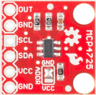
Pin Configuration and Descriptions
The MCP4725 is available in a 6-pin SOT-23 package. Below is the pinout and description:
| Pin | Name | Description |
|---|---|---|
| 1 | VDD | Power supply input (2.7V to 5.5V) |
| 2 | SDA | I2C data line |
| 3 | SCL | I2C clock line |
| 4 | GND | Ground |
| 5 | VOUT | Analog output voltage |
| 6 | A0 | I2C address selection (connect to GND or VDD) |
Usage Instructions
The MCP4725 is straightforward to use in a circuit, thanks to its I2C interface. Below are the steps and considerations for using the component:
Connecting the MCP4725
- Power Supply: Connect the VDD pin to a 3.3V or 5V power source, and the GND pin to ground.
- I2C Communication: Connect the SDA and SCL pins to the corresponding I2C pins on your microcontroller. Use pull-up resistors (typically 4.7kΩ) on both lines.
- Analog Output: Connect the VOUT pin to the desired load or circuit where the analog signal is required.
- Address Selection: Use the A0 pin to set the I2C address. Connect it to GND for the default address (0x60) or to VDD for an alternate address (0x61).
Example: Using MCP4725 with Arduino UNO
Below is an example of how to use the MCP4725 with an Arduino UNO to output a sine wave:
Circuit Diagram
- Connect MCP4725's VDD to Arduino's 5V pin.
- Connect MCP4725's GND to Arduino's GND.
- Connect MCP4725's SDA to Arduino's A4 (SDA).
- Connect MCP4725's SCL to Arduino's A5 (SCL).
- Use 4.7kΩ pull-up resistors on SDA and SCL lines.
Arduino Code
#include <Wire.h>
#include <Adafruit_MCP4725.h>

// Create an instance of the MCP4725 library
Adafruit_MCP4725 dac;

void setup() {
  // Initialize serial communication for debugging
  Serial.begin(9600);
  Serial.println("MCP4725 Test");

  // Initialize the DAC with the default I2C address (0x60)
  if (!dac.begin(0x60)) {
    Serial.println("Failed to find MCP4725. Check connections.");
    while (1);
  }
  Serial.println("MCP4725 initialized.");
}

void loop() {
  // Generate a sine wave and output it to the DAC
  for (int i = 0; i < 360; i++) {
    // Calculate the sine wave value (scaled to 12-bit range)
    uint16_t value = (sin(i * DEG_TO_RAD) + 1) * 2047.5;
    dac.setVoltage(value, false); // Send value to DAC, no EEPROM write
    delay(10); // Adjust delay for desired frequency
  }
}
Important Considerations
- EEPROM Usage: Writing to the EEPROM (persistent storage) is limited to 1,000,000 cycles. Avoid frequent writes to extend the component's lifespan.
- Voltage Range: Ensure the output load does not exceed the specified voltage and current limits.
- I2C Address Conflicts: If using multiple I2C devices, ensure their addresses do not conflict. Use the A0 pin to change the MCP4725's address if needed.
Troubleshooting and FAQs
Common Issues
No Output Voltage
- Cause: Incorrect I2C connections or address mismatch.
- Solution: Verify SDA and SCL connections. Check the I2C address in the code.
Erratic Output
- Cause: Missing or incorrect pull-up resistors on SDA and SCL lines.
- Solution: Add 4.7kΩ pull-up resistors to SDA and SCL.
EEPROM Write Fails
- Cause: Exceeded EEPROM write cycle limit.
- Solution: Use volatile writes (non-EEPROM) for frequent updates.
Device Not Detected
- Cause: Incorrect wiring or power supply issues.
- Solution: Check all connections and ensure VDD is within the specified range.
FAQs
Q: Can the MCP4725 output negative voltages?
A: No, the MCP4725 can only output voltages in the range of 0V to VDD.
Q: How do I increase the output resolution?
A: The MCP4725 already provides 12-bit resolution. For higher resolution, consider using a DAC with more bits.
Q: Can I use the MCP4725 with a 1.8V microcontroller?
A: Yes, but ensure the I2C lines are level-shifted to match the MCP4725's VDD (minimum 2.7V).
Q: Is the output voltage stable under varying loads?
A: The MCP4725 is designed for stable output, but ensure the load does not exceed 25mA. Use a buffer if needed.