
How to Use BASIC Stamp 1: Examples, Pinouts, and Specs
 Design with BASIC Stamp 1 in Cirkit Designer
Introduction
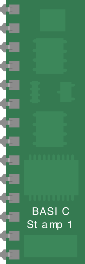
The BASIC Stamp 1 (BS1-IC), manufactured by Parallax Inc., is a compact microcontroller module designed for ease of use in programming and controlling electronic devices. It is particularly popular in educational environments and prototyping applications due to its simplicity and versatility. The BS1-IC is programmed using PBASIC, a beginner-friendly programming language, making it an excellent choice for hobbyists and students.
Explore Projects Built with BASIC Stamp 1
 Open Project in Cirkit Designer
 Open Project in Cirkit Designer
 Open Project in Cirkit Designer
 Open Project in Cirkit Designer
Explore Projects Built with BASIC Stamp 1
Open Project in Cirkit DesignerOpen Project in Cirkit DesignerOpen Project in Cirkit DesignerOpen Project in Cirkit DesignerCommon Applications and Use Cases
- Robotics and automation projects
- Educational tools for learning microcontroller programming
- Prototyping and proof-of-concept designs
- Simple control systems for LEDs, motors, and sensors
- Home automation and DIY electronics
Technical Specifications
The BASIC Stamp 1 is a self-contained microcontroller module with integrated memory, clock, and I/O capabilities. Below are its key technical details:
Key Technical Details
| Specification | Value |
|---|---|
| Manufacturer | Parallax Inc. |
| Part Number | BS1-IC |
| Operating Voltage | 5V DC |
| Current Consumption | 3 mA (typical) |
| Clock Speed | 4 MHz |
| Program Memory | 256 bytes |
| RAM | 16 bytes |
| I/O Pins | 8 (shared for input/output) |
| Programming Language | PBASIC |
| Dimensions | 1.2" x 0.6" (30.5mm x 15.2mm) |
Pin Configuration and Descriptions
The BS1-IC has an 8-pin DIP (Dual Inline Package) configuration. Below is the pinout and description:
| Pin Number | Name | Description |
|---|---|---|
| 1 | VSS | Ground (0V) |
| 2 | P0 | General-purpose I/O pin |
| 3 | P1 | General-purpose I/O pin |
| 4 | P2 | General-purpose I/O pin |
| 5 | P3 | General-purpose I/O pin |
| 6 | P4 | General-purpose I/O pin |
| 7 | P5 | General-purpose I/O pin |
| 8 | VDD | Power supply (5V DC) |
Usage Instructions
How to Use the BASIC Stamp 1 in a Circuit
- Power Supply: Connect the VDD pin to a regulated 5V DC power source and the VSS pin to ground.
- Programming: Use the Parallax BASIC Stamp Editor software to write PBASIC code. The BS1-IC is programmed via a serial connection using a compatible programming cable.
- Connecting Components: Attach sensors, LEDs, motors, or other peripherals to the I/O pins (P0–P5). Configure the pins as input or output in your PBASIC code.
- Running the Program: Once programmed, the BS1-IC will execute the code stored in its memory whenever powered on.
Important Considerations and Best Practices
- Voltage Levels: Ensure all connected components operate within the BS1-IC's 5V logic level to avoid damage.
- Current Limits: Each I/O pin can source or sink up to 20 mA. Use external transistors or relays for higher current loads.
- Decoupling Capacitor: Place a 0.1 µF capacitor between VDD and VSS to stabilize the power supply.
- Programming Cable: Use the official Parallax programming cable or a compatible adapter for reliable communication.
Example Code for Arduino-like Functionality
Below is an example PBASIC code to blink an LED connected to pin P0:
' BASIC Stamp 1 LED Blink Example
' This program blinks an LED connected to pin P0 every second.

Main:
  HIGH 0          ' Set P0 high to turn on the LED
  PAUSE 1000      ' Wait for 1 second
  LOW 0           ' Set P0 low to turn off the LED
  PAUSE 1000      ' Wait for 1 second
  GOTO Main       ' Repeat the loop
Troubleshooting and FAQs
Common Issues and Solutions
The BS1-IC is not responding to programming commands.
- Ensure the programming cable is securely connected to both the BS1-IC and the computer.
- Verify that the correct COM port is selected in the BASIC Stamp Editor software.
- Check the power supply to ensure the BS1-IC is receiving 5V DC.
The connected components are not functioning as expected.
- Double-check the wiring and ensure components are connected to the correct I/O pins.
- Verify that the PBASIC code correctly configures the pins as input or output.
- Ensure the components are compatible with the BS1-IC's 5V logic level.
The BS1-IC overheats or shuts down.
- Check for short circuits or excessive current draw on the I/O pins.
- Use external drivers for high-current devices like motors or relays.
FAQs
Q: Can the BS1-IC be powered by batteries?
A: Yes, the BS1-IC can be powered by a 5V regulated battery pack. Ensure the voltage is stable and within the operating range.
Q: How many I/O pins can I use simultaneously?
A: All 6 I/O pins (P0–P5) can be used simultaneously, but ensure the total current draw does not exceed the module's limits.
Q: Is the BS1-IC compatible with modern computers?
A: Yes, but you may need a USB-to-serial adapter if your computer lacks a serial port.
Q: Can I use the BS1-IC for real-time applications?
A: The BS1-IC is suitable for simple real-time tasks, but its 4 MHz clock speed and limited memory may not support complex real-time systems.
By following this documentation, users can effectively utilize the BASIC Stamp 1 for a wide range of projects and applications.