
How to Use DRV8833 Motor Driver: Examples, Pinouts, and Specs
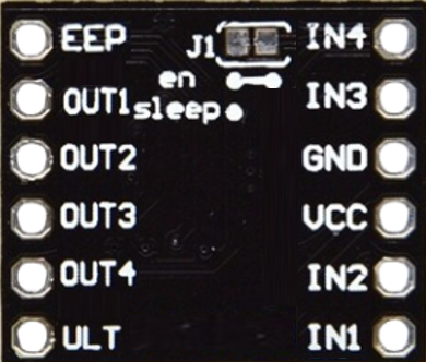
 Design with DRV8833 Motor Driver in Cirkit Designer
Introduction
The DRV8833 is a dual H-bridge motor driver designed to control two DC motors or one stepper motor. It provides bidirectional control and supports adjustable speed through Pulse Width Modulation (PWM) signals. Compact and efficient, the DRV8833 is ideal for battery-powered applications and robotics projects. Its built-in protection features, such as overcurrent and thermal shutdown, make it a reliable choice for motor control.
Explore Projects Built with DRV8833 Motor Driver
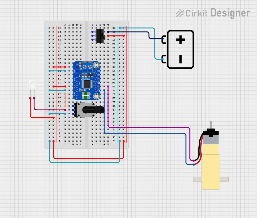 Open Project in Cirkit Designer
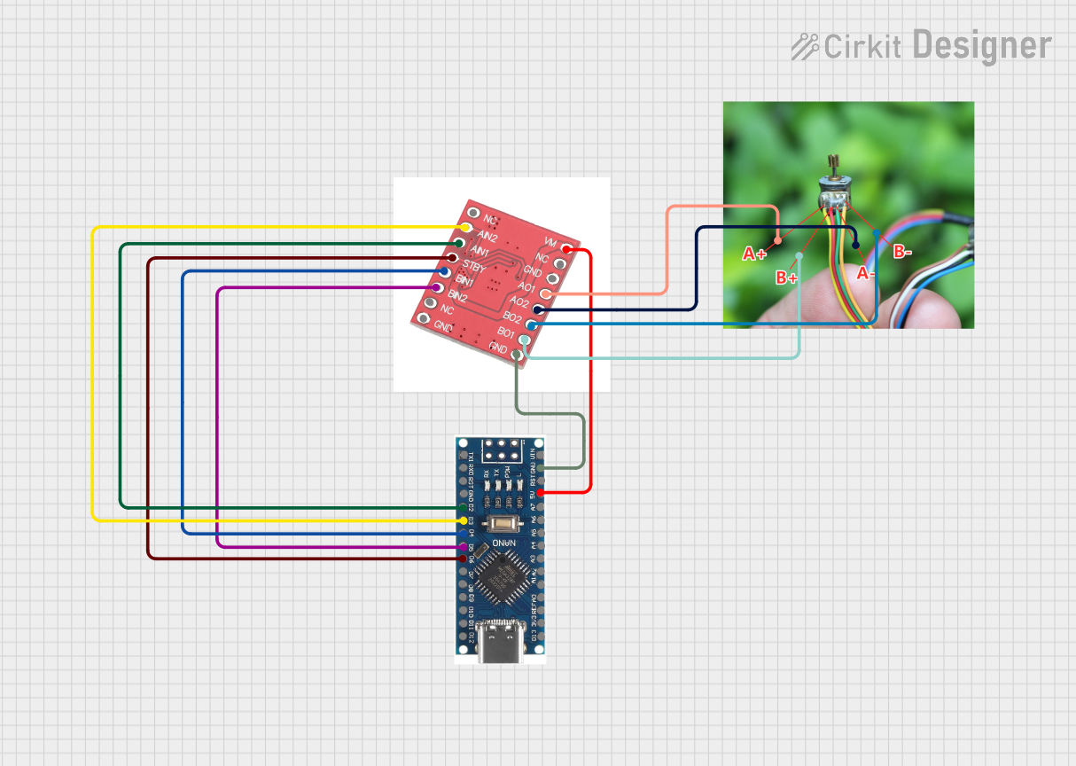 Open Project in Cirkit Designer
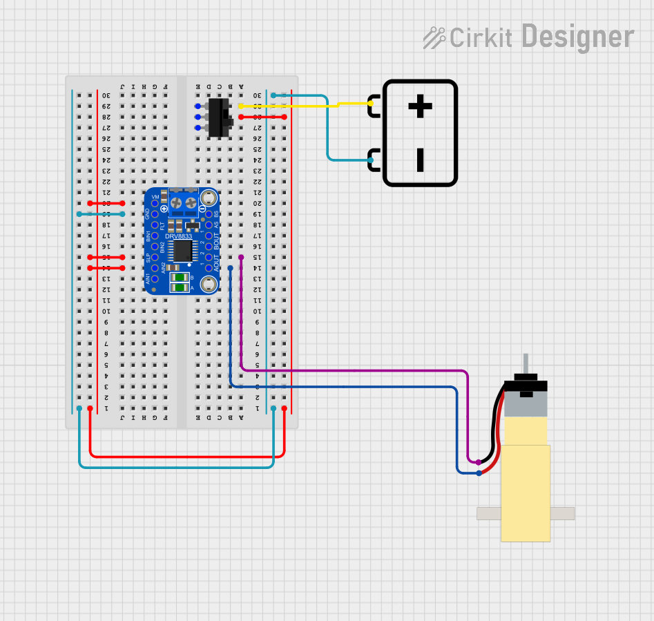 Open Project in Cirkit Designer
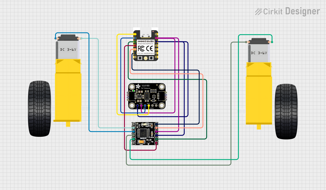 Open Project in Cirkit Designer
Explore Projects Built with DRV8833 Motor Driver
Open Project in Cirkit DesignerOpen Project in Cirkit DesignerOpen Project in Cirkit DesignerOpen Project in Cirkit DesignerCommon Applications
- Robotics and automation
- Remote-controlled vehicles
- Conveyor belts and small machinery
- DIY electronics projects
- Stepper motor control for 3D printers or CNC machines
Technical Specifications
The DRV8833 motor driver has the following key technical details:
| Parameter | Value |
|---|---|
| Operating Voltage (Vcc) | 2.7V to 10.8V |
| Motor Output Current | Up to 1.5A per channel (continuous) |
| Peak Current (per channel) | 2A (for short durations) |
| Logic Input Voltage | 0V to 5.5V |
| PWM Frequency | Up to 250 kHz |
| Thermal Shutdown | Yes |
| Overcurrent Protection | Yes |
| Operating Temperature | -40°C to 85°C |
Pin Configuration and Descriptions
The DRV8833 comes in a 16-pin package. Below is the pinout and description:
| Pin | Name | Description |
|---|---|---|
| 1 | AIN1 | Input 1 for H-Bridge A. Controls motor direction when paired with AIN2. |
| 2 | AIN2 | Input 2 for H-Bridge A. Controls motor direction when paired with AIN1. |
| 3 | BIN1 | Input 1 for H-Bridge B. Controls motor direction when paired with BIN2. |
| 4 | BIN2 | Input 2 for H-Bridge B. Controls motor direction when paired with BIN1. |
| 5 | VCC | Power supply for the motor driver (2.7V to 10.8V). |
| 6 | GND | Ground connection. |
| 7 | AOUT1 | Output 1 for H-Bridge A. Connect to one terminal of Motor A. |
| 8 | AOUT2 | Output 2 for H-Bridge A. Connect to the other terminal of Motor A. |
| 9 | BOUT1 | Output 1 for H-Bridge B. Connect to one terminal of Motor B. |
| 10 | BOUT2 | Output 2 for H-Bridge B. Connect to the other terminal of Motor B. |
| 11 | nSLEEP | Sleep mode input. Pull low to disable the driver and reduce power consumption. |
| 12 | nFAULT | Fault output. Active low when a fault condition occurs (e.g., overcurrent). |
| 13 | VMA | Motor power supply for H-Bridge A. |
| 14 | VMB | Motor power supply for H-Bridge B. |
| 15 | DECAY | Decay mode selection for current regulation. |
| 16 | NC | No connection. |
Usage Instructions
How to Use the DRV8833 in a Circuit
- Power Supply: Connect the motor power supply (2.7V to 10.8V) to the
VCCpin and ground to theGNDpin. Ensure the power supply can handle the current requirements of your motors. - Motor Connections: Connect the motor terminals to the output pins (
AOUT1,AOUT2for Motor A;BOUT1,BOUT2for Motor B). - Logic Inputs: Use the
AIN1,AIN2,BIN1, andBIN2pins to control the direction and speed of the motors. These pins accept logic levels (0V to 5.5V). - PWM Control: Apply PWM signals to the input pins to control motor speed. For example, a 50% duty cycle will run the motor at half speed.
- Sleep Mode: Pull the
nSLEEPpin low to put the driver into low-power sleep mode. Pull it high to enable normal operation. - Fault Monitoring: Monitor the
nFAULTpin for fault conditions. If it goes low, check for issues such as overcurrent or thermal shutdown.
Example: Connecting to an Arduino UNO
Below is an example of how to control a single DC motor using the DRV8833 and an Arduino UNO:
Circuit Connections
- Connect
AIN1to Arduino pin 9. - Connect
AIN2to Arduino pin 10. - Connect
nSLEEPto Arduino pin 8. - Connect
AOUT1andAOUT2to the motor terminals. - Connect
VCCto a 5V power supply andGNDto ground.
Arduino Code
// Define motor control pins
const int AIN1 = 9;  // Motor direction control pin 1
const int AIN2 = 10; // Motor direction control pin 2
const int nSLEEP = 8; // Sleep mode control pin

void setup() {
  // Set motor control pins as outputs
  pinMode(AIN1, OUTPUT);
  pinMode(AIN2, OUTPUT);
  pinMode(nSLEEP, OUTPUT);

  // Enable the motor driver by pulling nSLEEP high
  digitalWrite(nSLEEP, HIGH);
}

void loop() {
  // Rotate motor forward
  digitalWrite(AIN1, HIGH);
  digitalWrite(AIN2, LOW);
  delay(2000); // Run motor for 2 seconds

  // Stop motor
  digitalWrite(AIN1, LOW);
  digitalWrite(AIN2, LOW);
  delay(1000); // Pause for 1 second

  // Rotate motor backward
  digitalWrite(AIN1, LOW);
  digitalWrite(AIN2, HIGH);
  delay(2000); // Run motor for 2 seconds

  // Stop motor
  digitalWrite(AIN1, LOW);
  digitalWrite(AIN2, LOW);
  delay(1000); // Pause for 1 second
}
Important Considerations
- Ensure the motor power supply voltage matches the motor's specifications.
- Avoid exceeding the maximum current rating of 1.5A per channel to prevent damage.
- Use decoupling capacitors near the
VCCandGNDpins to reduce noise and improve stability. - If using PWM, ensure the frequency is within the supported range (up to 250 kHz).
Troubleshooting and FAQs
Common Issues
Motor Not Spinning
- Check the power supply connections and ensure the
nSLEEPpin is pulled high. - Verify the logic input signals (
AIN1,AIN2, etc.) are correctly configured.
- Check the power supply connections and ensure the
Motor Spins in the Wrong Direction
- Reverse the connections to the motor terminals or swap the logic levels on the input pins.
Overheating
- Ensure the motor current does not exceed the driver's maximum rating.
- Improve ventilation or add a heatsink to the driver.
nFAULT Pin is Low
- Check for overcurrent or thermal shutdown conditions.
- Reduce the motor load or allow the driver to cool down.
FAQs
Q: Can I use the DRV8833 to control a stepper motor?
A: Yes, the DRV8833 can control a bipolar stepper motor by using both H-bridges. You will need to sequence the inputs (AIN1, AIN2, BIN1, BIN2) appropriately to drive the stepper motor.
Q: What happens if I exceed the current rating?
A: The DRV8833 has built-in overcurrent protection. If the current exceeds the limit, the driver will shut down to prevent damage.
Q: Can I use a 3.3V microcontroller with the DRV8833?
A: Yes, the logic input pins are compatible with 3.3V and 5V logic levels.
Q: How do I select the decay mode?
A: The DECAY pin allows you to select the decay mode for current regulation. Refer to the datasheet for specific configurations.