How to Use Relay: Examples, Pinouts, and Specs
Introduction
A relay is an electromechanical switch that uses an electromagnetic coil to open or close a circuit, allowing control of a high-power circuit with a low-power signal. The Bestep 2 Channel Optocoupler Relay is a versatile module designed for applications requiring isolation between the control signal and the high-power circuit. It features optocoupler isolation for enhanced safety and reliability.
Explore Projects Built with Relay


Explore Projects Built with Relay
Common Applications and Use Cases
- Home automation systems (e.g., controlling lights, fans, or appliances)
- Industrial control systems
- Motor control
- Signal isolation in sensitive circuits
- IoT projects with microcontrollers like Arduino or Raspberry Pi
Technical Specifications
The following are the key technical details for the Bestep 2 Channel Optocoupler Relay:
General Specifications
- Operating Voltage: 5V DC
- Trigger Voltage: 3.3V to 5V (compatible with most microcontrollers)
- Relay Type: SPDT (Single Pole Double Throw)
- Maximum Load:
- AC: 250V at 10A
- DC: 30V at 10A
- Optocoupler Isolation: Yes
- Dimensions: 50mm x 40mm x 18mm
- Weight: ~30g
Pin Configuration and Descriptions
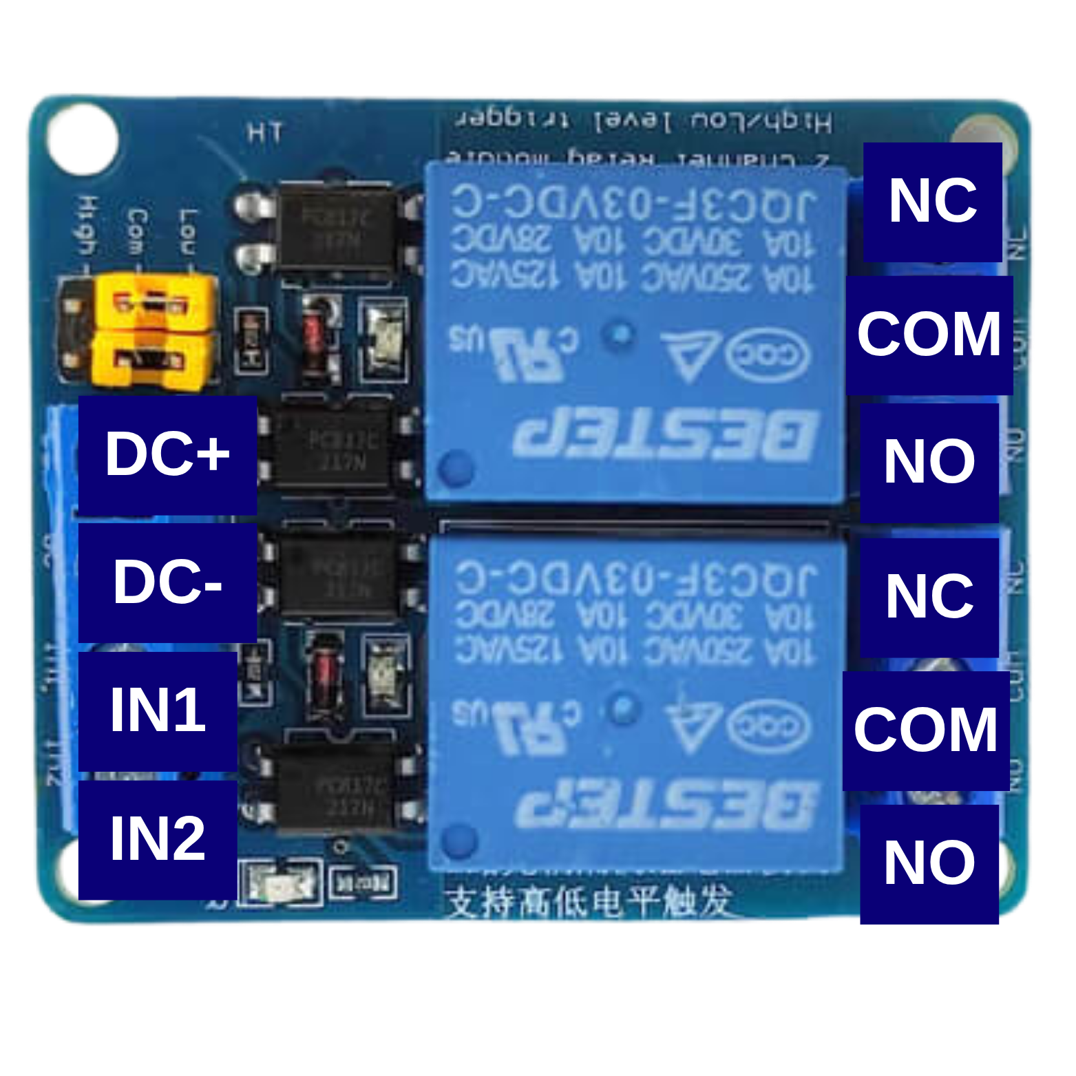
The module has two sets of pins: Input Pins for control signals and Output Terminals for the high-power circuit.
Input Pins
| Pin Name | Description |
|---|---|
| VCC | Connect to the 5V power supply. |
| GND | Connect to the ground of the power supply. |
| IN1 | Control signal for Relay 1. A HIGH signal activates the relay. |
| IN2 | Control signal for Relay 2. A HIGH signal activates the relay. |
Output Terminals (for each relay)
| Terminal Name | Description |
|---|---|
| COM | Common terminal for the relay. |
| NO | Normally Open terminal. Connect the load here if it should be OFF by default. |
| NC | Normally Closed terminal. Connect the load here if it should be ON by default. |
Usage Instructions
How to Use the Relay in a Circuit
- Power the Module: Connect the VCC pin to a 5V power supply and the GND pin to ground.
- Connect the Control Signal: Use a microcontroller (e.g., Arduino) to send a HIGH or LOW signal to the IN1 and IN2 pins to control the relays.
- Connect the Load:
- For a device that should be OFF by default, connect it between the NO terminal and COM.
- For a device that should be ON by default, connect it between the NC terminal and COM.
- Ensure Isolation: The optocoupler ensures electrical isolation between the control circuit and the high-power circuit, enhancing safety.
Important Considerations and Best Practices
- Power Supply: Ensure the module is powered with a stable 5V DC supply.
- Load Ratings: Do not exceed the maximum load ratings (250V AC/10A or 30V DC/10A).
- Flyback Diode: For inductive loads (e.g., motors), use a flyback diode across the load to protect the relay from voltage spikes.
- Signal Compatibility: Ensure the control signal voltage matches the relay's trigger voltage (3.3V to 5V).
- Avoid Overheating: Prolonged use with high-current loads may cause the relay to heat up. Use proper ventilation or heat dissipation methods.
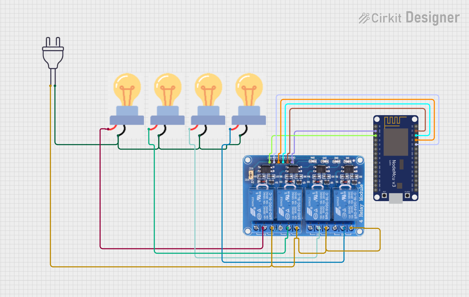
Example: Connecting to an Arduino UNO
Below is an example of how to control the Bestep 2 Channel Optocoupler Relay using an Arduino UNO.
Circuit Connections
- Connect the VCC pin of the relay module to the 5V pin on the Arduino.
- Connect the GND pin of the relay module to the GND pin on the Arduino.
- Connect the IN1 pin to Arduino digital pin 7.
- Connect the IN2 pin to Arduino digital pin 8.
- Connect a load (e.g., a light bulb) to the NO and COM terminals of Relay 1.
Arduino Code
// Define the relay control pins
const int relay1 = 7; // Relay 1 control pin
const int relay2 = 8; // Relay 2 control pin

void setup() {
  // Set relay pins as outputs
  pinMode(relay1, OUTPUT);
  pinMode(relay2, OUTPUT);

  // Initialize relays to OFF state
  digitalWrite(relay1, LOW); // Relay 1 OFF
  digitalWrite(relay2, LOW); // Relay 2 OFF
}

void loop() {
  // Turn Relay 1 ON for 2 seconds
  digitalWrite(relay1, HIGH); // Relay 1 ON
  delay(2000);                // Wait for 2 seconds

  // Turn Relay 1 OFF
  digitalWrite(relay1, LOW);  // Relay 1 OFF
  delay(2000);                // Wait for 2 seconds

  // Turn Relay 2 ON for 3 seconds
  digitalWrite(relay2, HIGH); // Relay 2 ON
  delay(3000);                // Wait for 3 seconds

  // Turn Relay 2 OFF
  digitalWrite(relay2, LOW);  // Relay 2 OFF
  delay(3000);                // Wait for 3 seconds
}
Troubleshooting and FAQs
Common Issues and Solutions
Relay Not Activating
- Cause: Insufficient control signal voltage.
- Solution: Ensure the control signal voltage is between 3.3V and 5V.
Load Not Turning ON/OFF
- Cause: Incorrect wiring of the load to the relay terminals.
- Solution: Verify the load is connected to the correct terminals (NO/NC and COM).
Relay Module Overheating
- Cause: Exceeding the maximum current rating.
- Solution: Ensure the load does not exceed 10A. Use a heat sink or cooling fan if necessary.
Interference with Microcontroller
- Cause: Electromagnetic interference from the relay.
- Solution: Use decoupling capacitors near the microcontroller and keep the relay module physically separated from sensitive components.
FAQs
Q: Can I use this relay module with a 3.3V microcontroller like ESP8266?
A: Yes, the module is compatible with 3.3V control signals.Q: Can I control AC and DC loads simultaneously?
A: Yes, as long as each relay is within its rated voltage and current limits.Q: Is the relay module safe for high-power applications?
A: Yes, but ensure proper isolation and do not exceed the rated load specifications.