Cirkit Designer Logo
Cirkit Designer
Your all-in-one circuit design IDE
Home / 
Component Documentation

How to Use LM3480IM4: Examples, Pinouts, and Specs

Image of LM3480IM4
Cirkit Designer LogoDesign with LM3480IM4 in Cirkit Designer

Introduction

The LM3480IM4 is a low dropout (LDO) linear voltage regulator designed to provide a stable output voltage with a low dropout voltage. This component is ideal for applications that require a regulated power supply with minimal voltage variation, such as battery-powered devices, portable electronics, and microcontroller systems.

Explore Projects Built with LM3480IM4

Use Cirkit Designer to design, explore, and prototype these projects online. Some projects support real-time simulation. Click "Open Project" to start designing instantly!
ESP32-Controlled Traffic Light and Multi-Motor Driver System
Image of Projeto final: A project utilizing LM3480IM4 in a practical application
This circuit features an ESP32 microcontroller connected to a traffic light module and multiple DC motors via two L298N motor drivers. The ESP32 controls the traffic light states and motor operations, likely for a model intersection with moving parts. The circuit also includes MT3608 boost converters to step up the voltage from a 4 x AAA battery mount to the required levels for the motor drivers, and an MG996R servo motor controlled directly by the ESP32.
Cirkit Designer LogoOpen Project in Cirkit Designer
ESP8266 and SIM800L Based GPS Tracker with I2C LCD Display and Battery Power
Image of Little Innovator Competition: A project utilizing LM3480IM4 in a practical application
This circuit integrates an ESP8266 NodeMCU microcontroller with a SIM800L GSM module, a GPS NEO 6M module, and a 16x2 I2C LCD display for communication and location tracking. It also includes a pushbutton for user input, a piezo buzzer for audio alerts, and is powered by a 2x 18650 battery pack through an LM2596 step-down module.
Cirkit Designer LogoOpen Project in Cirkit Designer
Raspberry Pi 4B-Based Multi-Sensor Interface Hub with GPS and GSM
Image of Rocket: A project utilizing LM3480IM4 in a practical application
This circuit features a Raspberry Pi 4B interfaced with an IMX296 color global shutter camera, a Neo 6M GPS module, an Adafruit BMP388 barometric pressure sensor, an MPU-6050 accelerometer/gyroscope, and a Sim800l GSM module for cellular connectivity. Power management is handled by an MT3608 boost converter, which steps up the voltage from a Lipo battery, with a resettable fuse PTC and a 1N4007 diode for protection. The Adafruit Perma-Proto HAT is used for organizing connections and interfacing the sensors and modules with the Raspberry Pi via I2C and GPIO pins.
Cirkit Designer LogoOpen Project in Cirkit Designer
ESP32-Based GPS and Sensor Data Logger with LoRa and NeoPixel Display
Image of CANSAT Firebeetle 2: A project utilizing LM3480IM4 in a practical application
This circuit integrates an ESP32 microcontroller with various sensors and communication modules, including a GPS module, BMP280 sensor, MPU6050 accelerometer, and gyroscope, as well as LoRa and APC220 communication modules. It also includes a NeoPixel LED stick and a micro SD card module for data storage. The circuit is designed for data acquisition, processing, and wireless transmission, powered by a 18650 Li-ion battery.
Cirkit Designer LogoOpen Project in Cirkit Designer

Explore Projects Built with LM3480IM4

Use Cirkit Designer to design, explore, and prototype these projects online. Some projects support real-time simulation. Click "Open Project" to start designing instantly!
Image of Projeto final: A project utilizing LM3480IM4 in a practical application
ESP32-Controlled Traffic Light and Multi-Motor Driver System
This circuit features an ESP32 microcontroller connected to a traffic light module and multiple DC motors via two L298N motor drivers. The ESP32 controls the traffic light states and motor operations, likely for a model intersection with moving parts. The circuit also includes MT3608 boost converters to step up the voltage from a 4 x AAA battery mount to the required levels for the motor drivers, and an MG996R servo motor controlled directly by the ESP32.
Cirkit Designer LogoOpen Project in Cirkit Designer
Image of Little Innovator Competition: A project utilizing LM3480IM4 in a practical application
ESP8266 and SIM800L Based GPS Tracker with I2C LCD Display and Battery Power
This circuit integrates an ESP8266 NodeMCU microcontroller with a SIM800L GSM module, a GPS NEO 6M module, and a 16x2 I2C LCD display for communication and location tracking. It also includes a pushbutton for user input, a piezo buzzer for audio alerts, and is powered by a 2x 18650 battery pack through an LM2596 step-down module.
Cirkit Designer LogoOpen Project in Cirkit Designer
Image of Rocket: A project utilizing LM3480IM4 in a practical application
Raspberry Pi 4B-Based Multi-Sensor Interface Hub with GPS and GSM
This circuit features a Raspberry Pi 4B interfaced with an IMX296 color global shutter camera, a Neo 6M GPS module, an Adafruit BMP388 barometric pressure sensor, an MPU-6050 accelerometer/gyroscope, and a Sim800l GSM module for cellular connectivity. Power management is handled by an MT3608 boost converter, which steps up the voltage from a Lipo battery, with a resettable fuse PTC and a 1N4007 diode for protection. The Adafruit Perma-Proto HAT is used for organizing connections and interfacing the sensors and modules with the Raspberry Pi via I2C and GPIO pins.
Cirkit Designer LogoOpen Project in Cirkit Designer
Image of CANSAT Firebeetle 2: A project utilizing LM3480IM4 in a practical application
ESP32-Based GPS and Sensor Data Logger with LoRa and NeoPixel Display
This circuit integrates an ESP32 microcontroller with various sensors and communication modules, including a GPS module, BMP280 sensor, MPU6050 accelerometer, and gyroscope, as well as LoRa and APC220 communication modules. It also includes a NeoPixel LED stick and a micro SD card module for data storage. The circuit is designed for data acquisition, processing, and wireless transmission, powered by a 18650 Li-ion battery.
Cirkit Designer LogoOpen Project in Cirkit Designer

Common Applications and Use Cases

  • Power supply for microcontrollers and digital logic
  • Battery-powered devices
  • Portable electronics
  • Low-power embedded systems

Technical Specifications

Key Technical Details

  • Output Voltage Options: Fixed
  • Dropout Voltage: Typically 0.5V at 100mA load
  • Output Current: Up to 100mA
  • Quiescent Current: Typically 1mA
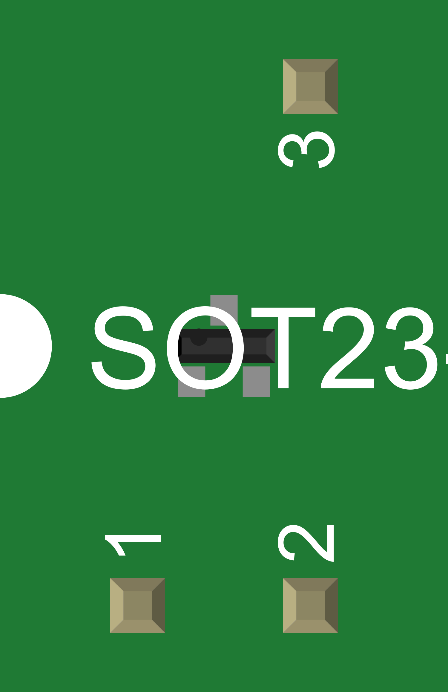
  • Package: SOT-23

Pin Configuration and Descriptions

Pin Number Name Description
1 GND Ground reference for the regulator
2 Vin Input voltage to the regulator
3 Vout Regulated output voltage

Usage Instructions

How to Use the Component in a Circuit

  1. Connect the input voltage (Vin) to pin 2. Ensure that the input voltage does not exceed the maximum rating specified in the datasheet.
  2. Connect the ground (GND) to pin 1.
  3. The regulated output voltage (Vout) can be taken from pin 3.
  4. It is recommended to place a bypass capacitor (typically 1µF) close to the input and output pins to improve stability and transient response.

Important Considerations and Best Practices

  • Ensure that the input voltage is always higher than the desired output voltage by at least the dropout voltage.
  • Avoid exceeding the maximum input voltage and current ratings to prevent damage to the regulator.
  • Heat dissipation should be considered if the regulator is expected to operate near its maximum output current rating.
  • Use appropriate decoupling capacitors to minimize voltage spikes and noise on the input and output.

Troubleshooting and FAQs

Common Issues Users Might Face

  • Output Voltage is Too Low: Check if the input voltage is sufficiently above the output voltage considering the dropout voltage.
  • Regulator Overheating: Ensure the current draw is within the specified limits and improve heat dissipation if necessary.
  • Output Voltage Fluctuations: Verify the presence and correct value of the input and output bypass capacitors.

Solutions and Tips for Troubleshooting

  • If the output voltage is not stable, check the input voltage and the bypass capacitors for proper values and connections.
  • In case of overheating, reduce the load current or improve heat sinking.
  • For noise issues, ensure that the layout minimizes the loop area and that the bypass capacitors are placed as close to the regulator pins as possible.

FAQs

Q: Can I use the LM3480IM4 to regulate a 5V output? A: Yes, as long as the input voltage is sufficiently above 5V considering the dropout voltage and within the maximum input voltage rating.

Q: What is the maximum input voltage for the LM3480IM4? A: Refer to the datasheet for the specific model's maximum input voltage rating.

Q: How can I improve the efficiency of the LM3480IM4? A: Minimize the difference between the input and output voltage to reduce power loss across the regulator.

Example Code for Arduino UNO

Below is an example code snippet for using the LM3480IM4 to power an Arduino UNO. The LM3480IM4 is used to regulate an external voltage source to the 5V required by the Arduino.

// This example assumes that the LM3480IM4 is used to provide a regulated 5V
// from a higher voltage source to power the Arduino UNO.

void setup() {
  // Initialize the serial communication to send data to the computer
  Serial.begin(9600);
}

void loop() {
  // Read the voltage on the 5V pin using the internal reference
  int sensorValue = analogRead(A0);
  float voltage = sensorValue * (5.0 / 1023.0);
  
  // Print the voltage to the Serial Monitor
  Serial.print("Regulated Voltage: ");
  Serial.print(voltage);
  Serial.println(" V");
  
  // Wait for a second before reading the voltage again
  delay(1000);
}

// Note: The analogRead function is used here for demonstration purposes.
// In practice, the Arduino's 5V pin would be directly powered by the LM3480IM4.

Remember to connect the output of the LM3480IM4 to the 5V pin on the Arduino and the ground of the LM3480IM4 to the ground on the Arduino. The input voltage should be connected to Vin on the LM3480IM4 and should be within the specified range for the regulator.