Cirkit Designer Logo
Cirkit Designer
Your all-in-one circuit design IDE
Home / 
Component Documentation

How to Use Adafruit Feather RP2040: Examples, Pinouts, and Specs

Image of Adafruit Feather RP2040
Cirkit Designer LogoDesign with Adafruit Feather RP2040 in Cirkit Designer

Introduction

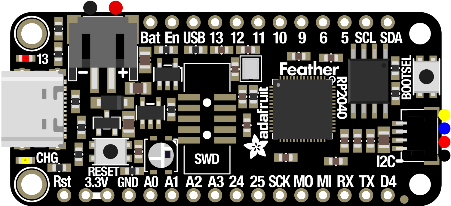
The Adafruit Feather RP2040 is a versatile and powerful development board that harnesses the capabilities of the Raspberry Pi RP2040 microcontroller. Designed with portability and affordability in mind, this board is part of the Feather ecosystem, known for its compact size and extensive I/O options. The RP2040 chip features a dual-core ARM Cortex-M0+ processor, providing ample computational power for a wide array of embedded projects, from DIY electronics to professional prototyping. Common applications include wearable devices, IoT applications, custom keyboards, and educational tools.

Explore Projects Built with Adafruit Feather RP2040

Use Cirkit Designer to design, explore, and prototype these projects online. Some projects support real-time simulation. Click "Open Project" to start designing instantly!
Adafruit QT Py RP2040 Development Board for Custom Projects
Image of perfboard: A project utilizing Adafruit Feather RP2040 in a practical application
The circuit consists of a single Adafruit QT Py RP2040 microcontroller with no external connections or additional components. It appears to be a standalone setup, possibly for initial testing or programming purposes.
Cirkit Designer LogoOpen Project in Cirkit Designer
Biometric and RFID Security System with Dual Adafruit Feather nRF52840 Controllers
Image of Rfid access control: A project utilizing Adafruit Feather RP2040 in a practical application
This circuit features two Adafruit Feather nRF52840 microcontrollers, each interfaced with an RFID-RC522 module for RFID communication and an AT24C256 external EEPROM for additional memory storage. One of the microcontrollers is also connected to an R307 Fingerprint Sensor for biometric input, and both microcontrollers are powered by a shared power supply and a coin cell breakout for backup or RTC power. The circuit is likely designed for secure access control or identification purposes, utilizing both RFID and fingerprint authentication, with data storage capabilities.
Cirkit Designer LogoOpen Project in Cirkit Designer
Solar-Powered Environmental Data Logger with Adafruit Feather M0 Express
Image of Lake Thoreau Monitoring Station: A project utilizing Adafruit Feather RP2040 in a practical application
This circuit is designed for environmental data collection and logging, utilizing an Adafruit Feather M0 Express microcontroller as the central processing unit. It interfaces with a BME280 sensor for atmospheric temperature, humidity, and pressure measurements, an SGP30 sensor for monitoring air quality (eCO2 and TVOC), and a STEMMA soil sensor for detecting soil moisture and temperature. The system is powered by a solar panel and a 3.7v LiPo battery, managed by an Adafruit BQ24074 Solar-DC-USB Lipo Charger, and provides easy access to the microcontroller's connections through an Adafruit Terminal Breakout FeatherWing.
Cirkit Designer LogoOpen Project in Cirkit Designer
Battery-Powered Smart Sensor Hub with Adafruit QT Py RP2040
Image of wearable final: A project utilizing Adafruit Feather RP2040 in a practical application
This circuit features an Adafruit QT Py RP2040 microcontroller interfaced with an APDS9960 proximity sensor, an MPU6050 accelerometer and gyroscope, and an OLED display via I2C communication. It also includes a buzzer controlled by the microcontroller and is powered by a 3.7V LiPo battery with a toggle switch for power control.
Cirkit Designer LogoOpen Project in Cirkit Designer

Explore Projects Built with Adafruit Feather RP2040

Use Cirkit Designer to design, explore, and prototype these projects online. Some projects support real-time simulation. Click "Open Project" to start designing instantly!
Image of perfboard: A project utilizing Adafruit Feather RP2040 in a practical application
Adafruit QT Py RP2040 Development Board for Custom Projects
The circuit consists of a single Adafruit QT Py RP2040 microcontroller with no external connections or additional components. It appears to be a standalone setup, possibly for initial testing or programming purposes.
Cirkit Designer LogoOpen Project in Cirkit Designer
Image of Rfid access control: A project utilizing Adafruit Feather RP2040 in a practical application
Biometric and RFID Security System with Dual Adafruit Feather nRF52840 Controllers
This circuit features two Adafruit Feather nRF52840 microcontrollers, each interfaced with an RFID-RC522 module for RFID communication and an AT24C256 external EEPROM for additional memory storage. One of the microcontrollers is also connected to an R307 Fingerprint Sensor for biometric input, and both microcontrollers are powered by a shared power supply and a coin cell breakout for backup or RTC power. The circuit is likely designed for secure access control or identification purposes, utilizing both RFID and fingerprint authentication, with data storage capabilities.
Cirkit Designer LogoOpen Project in Cirkit Designer
Image of Lake Thoreau Monitoring Station: A project utilizing Adafruit Feather RP2040 in a practical application
Solar-Powered Environmental Data Logger with Adafruit Feather M0 Express
This circuit is designed for environmental data collection and logging, utilizing an Adafruit Feather M0 Express microcontroller as the central processing unit. It interfaces with a BME280 sensor for atmospheric temperature, humidity, and pressure measurements, an SGP30 sensor for monitoring air quality (eCO2 and TVOC), and a STEMMA soil sensor for detecting soil moisture and temperature. The system is powered by a solar panel and a 3.7v LiPo battery, managed by an Adafruit BQ24074 Solar-DC-USB Lipo Charger, and provides easy access to the microcontroller's connections through an Adafruit Terminal Breakout FeatherWing.
Cirkit Designer LogoOpen Project in Cirkit Designer
Image of wearable final: A project utilizing Adafruit Feather RP2040 in a practical application
Battery-Powered Smart Sensor Hub with Adafruit QT Py RP2040
This circuit features an Adafruit QT Py RP2040 microcontroller interfaced with an APDS9960 proximity sensor, an MPU6050 accelerometer and gyroscope, and an OLED display via I2C communication. It also includes a buzzer controlled by the microcontroller and is powered by a 3.7V LiPo battery with a toggle switch for power control.
Cirkit Designer LogoOpen Project in Cirkit Designer

Technical Specifications

Key Features

  • Microcontroller: Raspberry Pi RP2040
  • Processor: Dual-core ARM Cortex-M0+ @ 133MHz
  • Memory: 264KB of SRAM, and 2MB of onboard Flash memory
  • USB: Native USB support
  • GPIO: 21x GPIO pins
  • Analog Inputs: 4x 12-bit ADC channels
  • UART, I2C, SPI: Available
  • PWM Outputs: Available on all GPIO pins
  • Power Supply: USB-C or LiPo battery (with built-in charging circuit)
  • Dimensions: 51mm x 23mm x 8mm (without headers)

Pin Configuration

Pin Number Function Description
1 3V3 3.3V power supply output
2-13 GPIO 0-11 General-purpose I/O pins
14 EN Enable pin for the 3.3V regulator
15 VBAT Battery voltage input for LiPo batteries
16 USB USB power input/output
17-20 SCK, MO, MI, CS SPI default pins
21-22 SDA, SCL I2C default pins
23-24 TX, RX UART default pins
25 A0 Analog input channel 0
26-28 A1-A3 Additional analog input channels
29 BUSY Flash memory busy status
30 GND Ground

Usage Instructions

Setting Up the Adafruit Feather RP2040

  1. Connect the board to your computer using a USB-C cable.
  2. Install the necessary drivers and board support package for the RP2040 in your preferred development environment, such as the Arduino IDE or Thonny Python IDE.
  3. Select the Adafruit Feather RP2040 from the list of available boards.

Circuit Integration

  • Ensure that the power supply does not exceed the recommended voltage levels.
  • Connect peripherals to the GPIO pins, taking note of the pin functions and current limitations.
  • Use the onboard ADC channels for analog sensors, and configure the SPI, I2C, or UART pins for communication with other devices.

Best Practices

  • Always disconnect the board from power sources before making or altering connections.
  • Use a current limiting resistor with LEDs to prevent damage.
  • Avoid drawing more than 50mA from any GPIO pin.
  • Utilize the built-in LED on pin 13 for debugging purposes.

Example Code for Arduino UNO

Here is a simple example of blinking an LED connected to pin 13 of the Adafruit Feather RP2040 using Arduino code:

// Define the LED pin
const int ledPin = 13;

void setup() {
  // Initialize the LED pin as an output
  pinMode(ledPin, OUTPUT);
}

void loop() {
  // Turn the LED on
  digitalWrite(ledPin, HIGH);
  // Wait for one second
  delay(1000);
  // Turn the LED off
  digitalWrite(ledPin, LOW);
  // Wait for one second
  delay(1000);
}

Troubleshooting and FAQs

Common Issues

  • Board not recognized: Ensure that the USB cable is properly connected and that the board is selected in your development environment.
  • Failed to upload sketch: Check the USB cable and ensure that the correct board and port are selected. Also, verify that the bootloader is not corrupted.
  • I/O pin not functioning: Confirm that the pin is not being used by another process and that it is configured correctly in your code.

FAQs

Q: Can I power the Adafruit Feather RP2040 with a battery? A: Yes, you can power it with a LiPo battery, and it includes a built-in charging circuit.

Q: What is the maximum voltage for the analog input pins? A: The maximum voltage for the analog pins is 3.3V.

Q: How do I reset the board? A: Briefly press the reset button on the board to reset it.

Q: Can I use CircuitPython with this board? A: Yes, the Adafruit Feather RP2040 supports CircuitPython.

For further assistance, consult the Adafruit Feather RP2040 forums and the extensive online resources available from Adafruit.