How to Use MD13S: Examples, Pinouts, and Specs
Introduction
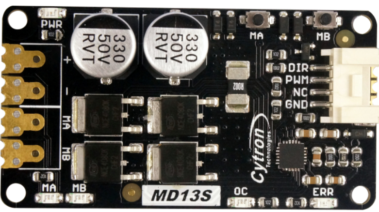
The MD13S, manufactured by Cytron, is a compact and efficient DC motor driver designed for controlling the speed and direction of small DC motors. It features an H-bridge configuration, enabling bidirectional motor control. With its low power consumption and ease of use, the MD13S is ideal for robotics, automation, and other motor control applications. Its compact design makes it suitable for projects with space constraints, while its robust performance ensures reliable operation.
Explore Projects Built with MD13S


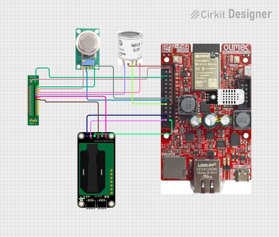
Explore Projects Built with MD13S
Common Applications
- Robotics: Driving wheels or actuators in robotic systems.
- Automation: Controlling conveyor belts, fans, or other small DC motor-driven mechanisms.
- DIY Projects: Ideal for hobbyists building motorized systems.
- Educational Use: Teaching motor control concepts in electronics and robotics.
Technical Specifications
Key Technical Details
| Parameter | Value |
|---|---|
| Operating Voltage | 6V to 30V |
| Continuous Current | 13A |
| Peak Current | 30A (for a few seconds) |
| Control Signal Voltage | 3.3V or 5V logic compatible |
| PWM Frequency | Up to 20 kHz |
| Motor Type Supported | Brushed DC motors |
| Dimensions | 62mm x 42mm x 15mm |
| Weight | 30g |
Pin Configuration and Descriptions
The MD13S has a simple pinout for easy integration into your circuit. Below is the pin configuration:
| Pin Name | Type | Description |
|---|---|---|
| VM | Power | Motor power supply input (6V to 30V). |
| GND | Power | Ground connection for the motor power supply. |
| M+ | Output | Positive terminal of the motor connection. |
| M- | Output | Negative terminal of the motor connection. |
| PWM | Input | Pulse Width Modulation (PWM) signal for speed control (3.3V/5V logic). |
| DIR | Input | Direction control signal (3.3V/5V logic). |
| GND | Power | Ground connection for the control signals. |
Usage Instructions
How to Use the MD13S in a Circuit
- Power Supply: Connect the motor power supply (6V to 30V) to the
VMpin and the ground to theGNDpin. - Motor Connection: Attach the DC motor terminals to the
M+andM-pins. - Control Signals:
- Connect the
PWMpin to a PWM-capable output pin of your microcontroller (e.g., Arduino). - Connect the
DIRpin to a digital output pin of your microcontroller to control the motor's direction. - Ensure the control signal ground is connected to the
GNDpin of the MD13S.
- Connect the
- Logic Level Compatibility: The MD13S supports both 3.3V and 5V logic levels, making it compatible with most microcontrollers.
Important Considerations
- Heat Dissipation: The MD13S can handle up to 13A continuously, but ensure proper ventilation or heat sinking for high-current applications.
- PWM Frequency: Use a PWM frequency of up to 20 kHz for optimal performance.
- Reverse Polarity Protection: The MD13S does not have built-in reverse polarity protection. Double-check your connections before powering the circuit.
Example: Using MD13S with Arduino UNO
Below is an example Arduino sketch to control the speed and direction of a DC motor using the MD13S:
// Define pin connections
const int pwmPin = 9;  // PWM pin connected to MD13S PWM input
const int dirPin = 8;  // Direction pin connected to MD13S DIR input

void setup() {
  // Set pin modes
  pinMode(pwmPin, OUTPUT);
  pinMode(dirPin, OUTPUT);
}

void loop() {
  // Rotate motor in one direction at 50% speed
  digitalWrite(dirPin, HIGH);  // Set direction
  analogWrite(pwmPin, 128);    // Set speed (128/255 = ~50%)
  delay(2000);                 // Run for 2 seconds

  // Stop the motor
  analogWrite(pwmPin, 0);      // Set speed to 0
  delay(1000);                 // Wait for 1 second

  // Rotate motor in the opposite direction at 75% speed
  digitalWrite(dirPin, LOW);   // Change direction
  analogWrite(pwmPin, 192);    // Set speed (192/255 = ~75%)
  delay(2000);                 // Run for 2 seconds

  // Stop the motor
  analogWrite(pwmPin, 0);      // Set speed to 0
  delay(1000);                 // Wait for 1 second
}
Troubleshooting and FAQs
Common Issues and Solutions
Motor Not Running:
- Cause: Incorrect wiring or loose connections.
- Solution: Double-check all connections, especially the motor and power supply.
Motor Running in the Wrong Direction:
- Cause: Incorrect
DIRsignal or reversed motor connections. - Solution: Verify the
DIRsignal logic or swap the motor connections (M+andM-).
- Cause: Incorrect
Overheating:
- Cause: Prolonged operation at high current without proper cooling.
- Solution: Add a heat sink or improve ventilation around the MD13S.
PWM Signal Not Detected:
- Cause: Incorrect PWM frequency or incompatible logic level.
- Solution: Ensure the PWM frequency is within the supported range (up to 20 kHz) and the logic level matches (3.3V or 5V).
FAQs
Can I use the MD13S with a 3.3V microcontroller like the Raspberry Pi? Yes, the MD13S is compatible with both 3.3V and 5V logic levels.
What happens if I exceed the 30A peak current? Exceeding the peak current may damage the MD13S. Always ensure your motor's current draw is within the specified limits.
Can I control two motors with one MD13S? No, the MD13S is designed to control a single brushed DC motor.
Is reverse polarity protection included? No, the MD13S does not have reverse polarity protection. Ensure correct power supply polarity to avoid damage.
This concludes the documentation for the Cytron MD13S motor driver.