How to Use 5 pin: Examples, Pinouts, and Specs
Introduction
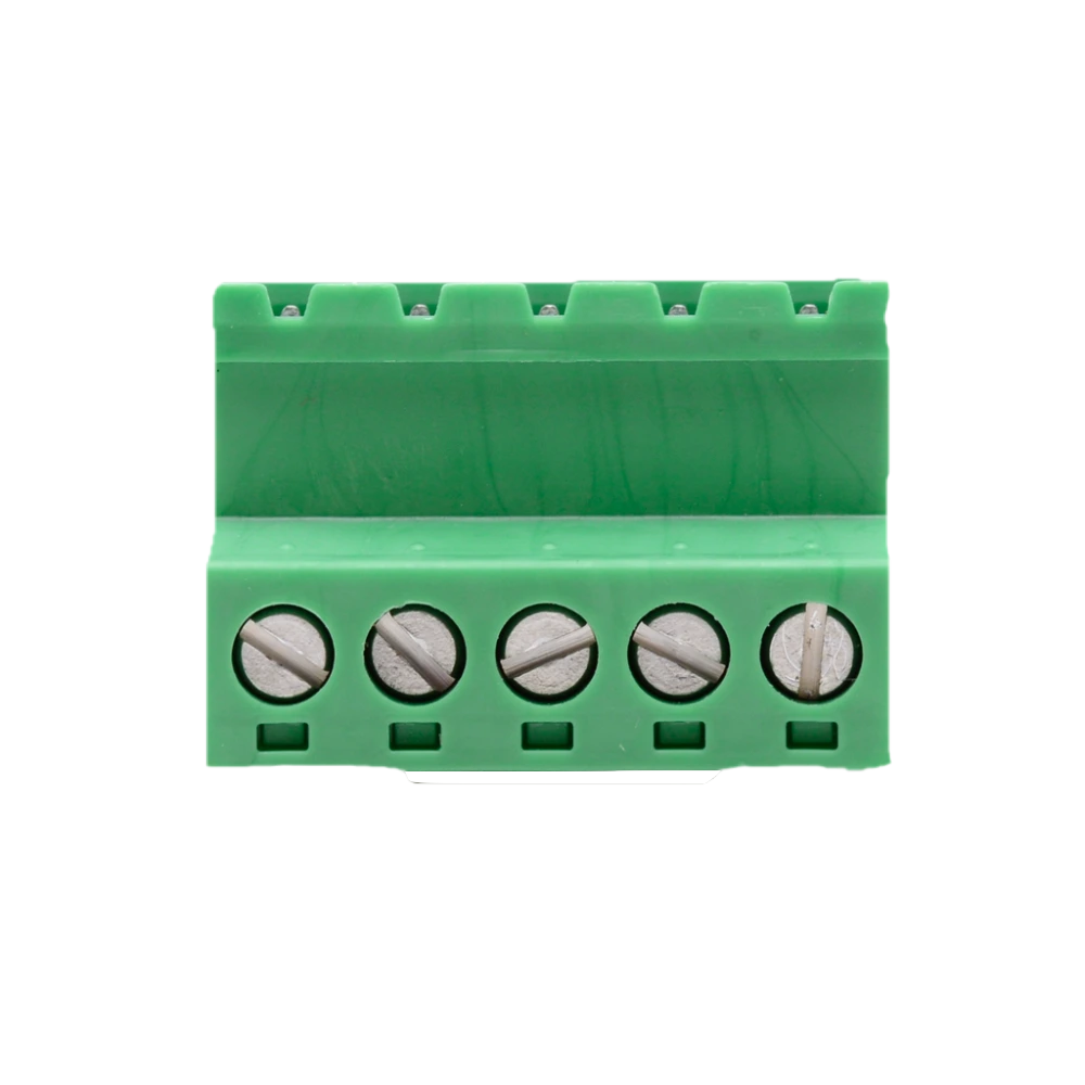
A 5 pin connector is a type of electrical connector that features five pins for establishing electrical connections. These connectors are commonly used in circuits for signal transmission, power distribution, or both. They are versatile and can be found in a wide range of applications, including audio equipment, industrial machinery, automotive systems, and consumer electronics. Their design ensures reliable connections and easy integration into various systems.
Explore Projects Built with 5 pin


Explore Projects Built with 5 pin
Technical Specifications
Below are the general technical specifications for a standard 5 pin connector. Note that specific values may vary depending on the manufacturer and model.
- Number of Pins: 5
- Current Rating: Typically 1A to 10A (depending on the type and size)
- Voltage Rating: Up to 250V (varies by model)
- Contact Resistance: ≤ 30 mΩ
- Insulation Resistance: ≥ 1000 MΩ
- Operating Temperature: -40°C to +85°C (varies by material)
- Connector Type: Male/Female (plug/socket)
- Mounting Style: Panel mount, PCB mount, or cable mount
Pin Configuration and Descriptions
The pin configuration of a 5 pin connector depends on its application. Below is a general example of pin assignments for a 5 pin connector used in signal transmission:
| Pin Number | Description | Common Use |
|---|---|---|
| 1 | Ground (GND) | Reference ground for the circuit |
| 2 | Power Supply (VCC) | Provides power to the circuit |
| 3 | Signal Line 1 (S1) | Transmits data or control signal |
| 4 | Signal Line 2 (S2) | Transmits data or control signal |
| 5 | Signal Line 3 (S3) | Transmits data or control signal |
Note: The exact pinout may vary depending on the specific application or manufacturer. Always refer to the datasheet or documentation for your specific connector.
Usage Instructions
How to Use the 5 Pin Connector in a Circuit
- Identify the Pinout: Refer to the datasheet or labeling on the connector to identify the function of each pin.
- Prepare the Wires: Strip the insulation from the wires you intend to connect, ensuring the exposed length matches the connector's requirements.
- Solder or Crimp: Depending on the connector type, solder the wires to the pins or use a crimping tool to attach them securely.
- Connect to the Circuit: Plug the connector into its corresponding socket or mount it onto a PCB as required.
- Test the Connection: Verify the connections using a multimeter to ensure proper continuity and functionality.
Important Considerations and Best Practices
- Match the Connector Type: Ensure the male and female connectors are compatible.
- Avoid Overloading: Do not exceed the current or voltage ratings of the connector.
- Secure Connections: Use locking mechanisms (if available) to prevent accidental disconnection.
- Protect Against Moisture: For outdoor or industrial applications, use waterproof or sealed connectors.
- Check for Polarity: Ensure the correct orientation of the connector to avoid damage to the circuit.
Example: Connecting a 5 Pin Connector to an Arduino UNO
Below is an example of how to use a 5 pin connector to interface with an Arduino UNO for signal transmission:
// Example: Reading signals from a 5 pin connector using Arduino UNO

// Define pin assignments for the 5 pin connector
const int signalPin1 = 2; // Signal Line 1 connected to Arduino pin 2
const int signalPin2 = 3; // Signal Line 2 connected to Arduino pin 3
const int signalPin3 = 4; // Signal Line 3 connected to Arduino pin 4

void setup() {
  // Initialize serial communication for debugging
  Serial.begin(9600);

  // Set signal pins as input
  pinMode(signalPin1, INPUT);
  pinMode(signalPin2, INPUT);
  pinMode(signalPin3, INPUT);
}

void loop() {
  // Read the state of each signal pin
  int signal1 = digitalRead(signalPin1);
  int signal2 = digitalRead(signalPin2);
  int signal3 = digitalRead(signalPin3);

  // Print the signal states to the Serial Monitor
  Serial.print("Signal 1: ");
  Serial.println(signal1);
  Serial.print("Signal 2: ");
  Serial.println(signal2);
  Serial.print("Signal 3: ");
  Serial.println(signal3);

  // Add a short delay to avoid flooding the Serial Monitor
  delay(500);
}
Note: Ensure the 5 pin connector is properly wired to the Arduino UNO, with the ground pin connected to the Arduino's GND.
Troubleshooting and FAQs
Common Issues and Solutions
Loose Connections:
- Issue: The connector is not securely attached, causing intermittent signals.
- Solution: Ensure the connector is fully seated and locked (if applicable). Check for damaged pins or sockets.
Incorrect Pinout:
- Issue: The pins are connected incorrectly, leading to malfunction.
- Solution: Double-check the pinout using the datasheet or labeling on the connector.
Overheating:
- Issue: The connector becomes hot during operation.
- Solution: Verify that the current and voltage do not exceed the connector's ratings. Use a larger connector if necessary.
Signal Interference:
- Issue: Noise or interference affects signal quality.
- Solution: Use shielded cables and ensure proper grounding.
Corrosion or Dirt:
- Issue: Poor contact due to corrosion or debris on the pins.
- Solution: Clean the pins with isopropyl alcohol and a soft brush. Replace the connector if necessary.
FAQs
Q: Can I use a 5 pin connector for both power and data?
- A: Yes, many 5 pin connectors are designed to handle both power and data. Ensure the pins are assigned appropriately and the ratings are not exceeded.
Q: Are 5 pin connectors waterproof?
- A: Not all 5 pin connectors are waterproof. For outdoor or harsh environments, use connectors with an IP67 or higher rating.
Q: How do I identify the pinout of an unmarked 5 pin connector?
- A: Use a multimeter to test continuity and determine the function of each pin. Consult the device's documentation if available.
Q: Can I use a 5 pin connector with fewer wires?
- A: Yes, unused pins can be left unconnected, but ensure they do not short-circuit with other pins.
By following this documentation, you can effectively use and troubleshoot a 5 pin connector in your projects.