How to Use L298N Dual H-Bridge Motor Driver: Examples, Pinouts, and Specs
Introduction
The L298N Dual H-Bridge Motor Driver, manufactured by Handson Technology (Part ID: Motor Driver), is a versatile and robust motor driver module. It is designed to control the direction and speed of two DC motors or one stepper motor using Pulse Width Modulation (PWM) signals. The module is capable of handling up to 2A per channel and operates with a supply voltage range of 5V to 35V, making it suitable for a wide range of motor control applications.
Explore Projects Built with L298N Dual H-Bridge Motor Driver
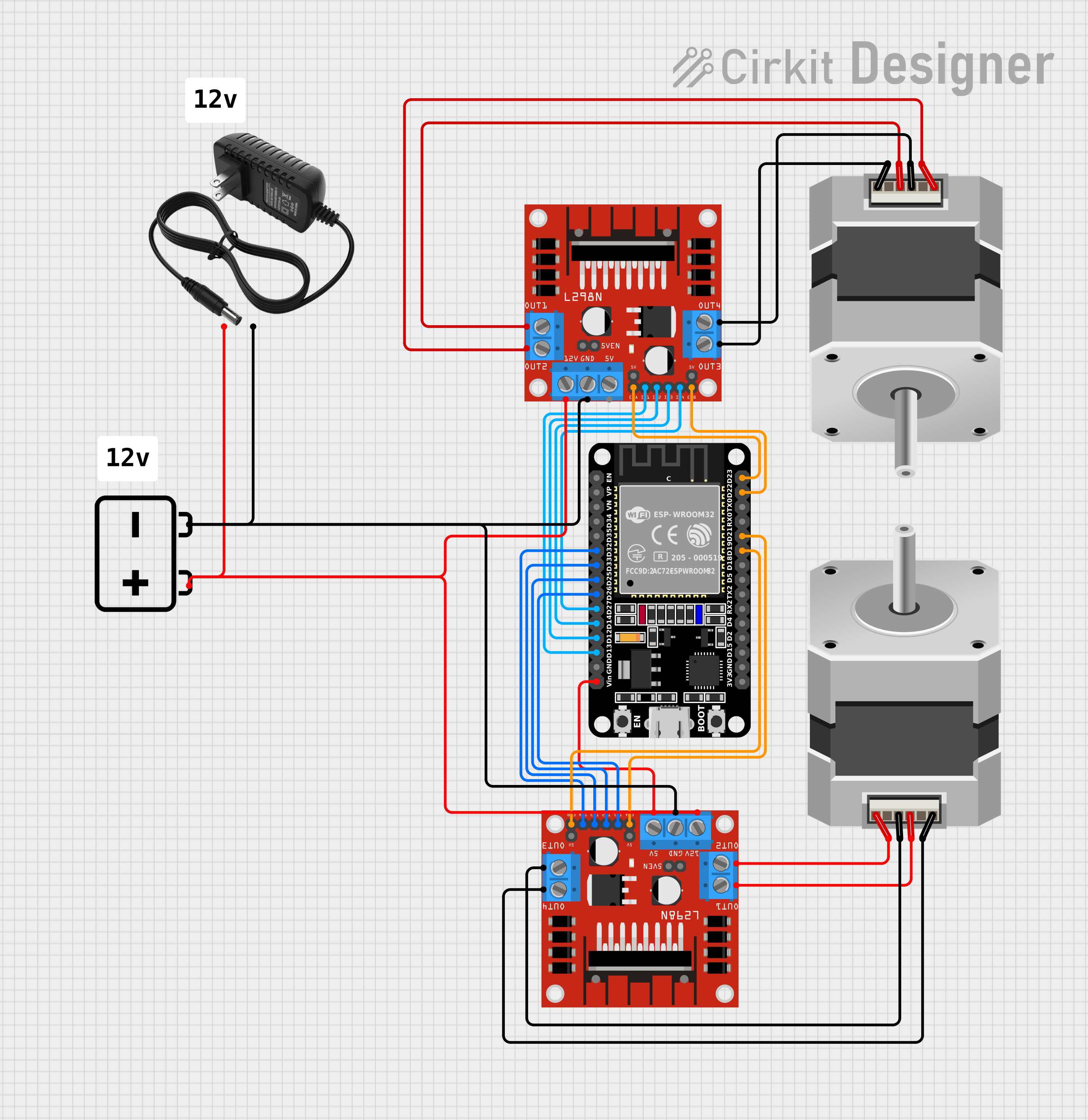
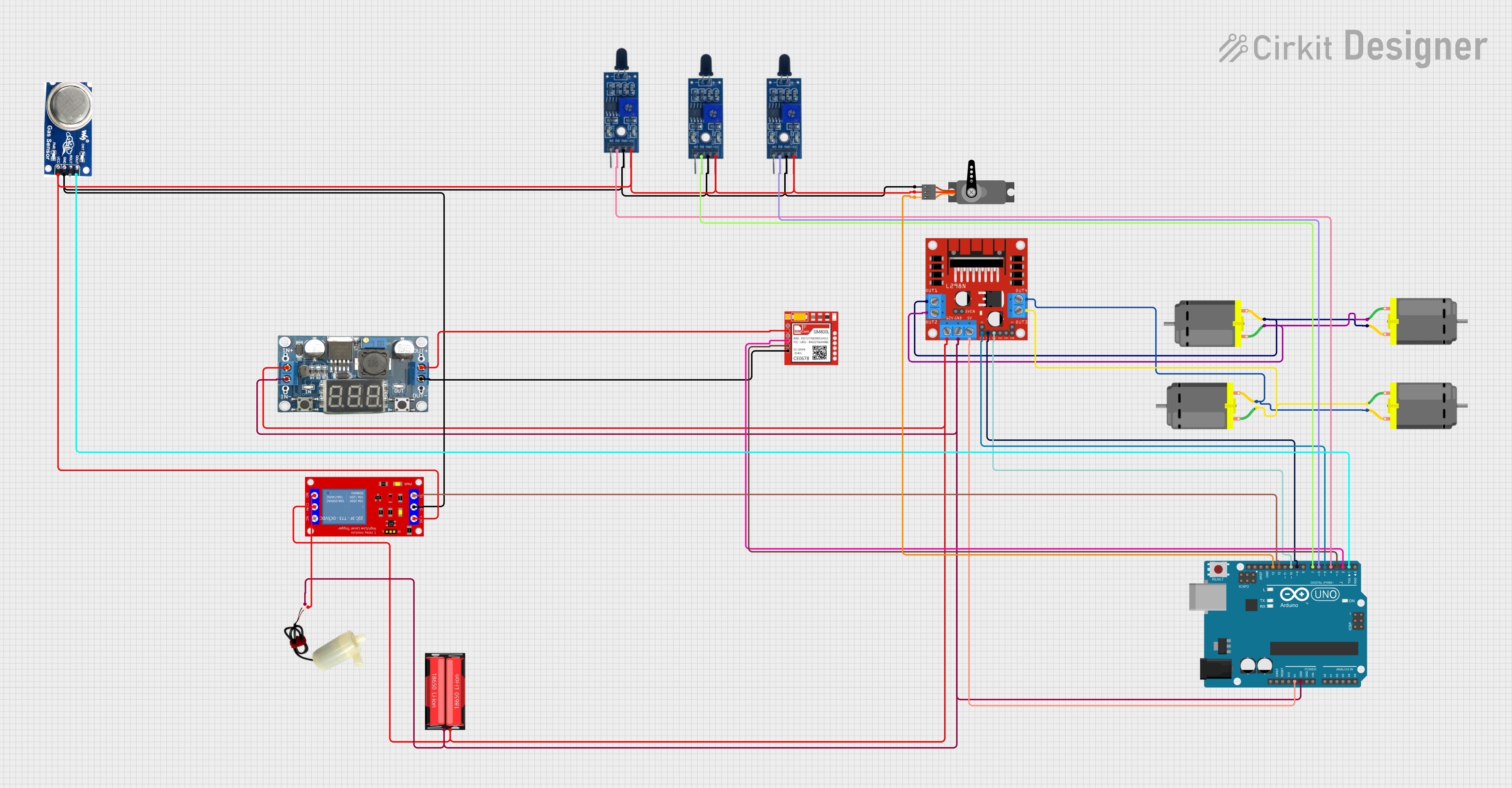


Explore Projects Built with L298N Dual H-Bridge Motor Driver
Common Applications and Use Cases
- Robotics: Driving wheels or actuators in robotic systems.
- Automation: Controlling conveyor belts or other motorized systems.
- DIY Projects: Building remote-controlled cars, drones, or other motorized devices.
- Stepper Motor Control: Driving stepper motors in CNC machines or 3D printers.
Technical Specifications
The following table outlines the key technical details of the L298N Dual H-Bridge Motor Driver:
| Parameter | Value |
|---|---|
| Supply Voltage (Vcc) | 5V to 35V |
| Logic Voltage (Vss) | 5V |
| Maximum Current (per channel) | 2A |
| Number of Channels | 2 |
| Control Signals | PWM, Direction (IN1, IN2, IN3, IN4) |
| Output Type | H-Bridge |
| Heat Dissipation | Built-in heatsink |
| Dimensions | 43mm x 43mm x 27mm |
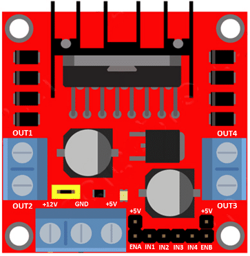
Pin Configuration and Descriptions
The L298N module has several pins and terminals for power, control, and motor connections. The table below describes each pin:
| Pin/Terminal | Description |
|---|---|
| Vcc | Power supply for motors (5V to 35V). |
| GND | Ground connection. |
| 5V | Regulated 5V output (can be used to power logic circuits if Vcc > 7V). |
| IN1, IN2 | Control inputs for Motor A. IN1 and IN2 determine the direction of rotation. |
| IN3, IN4 | Control inputs for Motor B. IN3 and IN4 determine the direction of rotation. |
| ENA | Enable pin for Motor A. Can be connected to a PWM signal for speed control. |
| ENB | Enable pin for Motor B. Can be connected to a PWM signal for speed control. |
| OUT1, OUT2 | Motor A output terminals. |
| OUT3, OUT4 | Motor B output terminals. |
Usage Instructions
How to Use the L298N in a Circuit
Power Connections:
- Connect the motor power supply to the
Vccterminal (5V to 35V). - Connect the ground of the power supply to the
GNDterminal. - If the motor power supply is greater than 7V, the onboard voltage regulator will provide 5V to the
5Vpin, which can be used to power external logic circuits.
- Connect the motor power supply to the
Motor Connections:
- Connect the terminals of Motor A to
OUT1andOUT2. - Connect the terminals of Motor B to
OUT3andOUT4.
- Connect the terminals of Motor A to
Control Connections:
- Connect the control pins (
IN1,IN2,IN3,IN4) to the microcontroller's GPIO pins. - Connect the enable pins (
ENA,ENB) to PWM-capable GPIO pins for speed control.
- Connect the control pins (
Logic Power:
- If the motor power supply is less than 7V, connect an external 5V power source to the
5Vpin to power the logic circuitry.
- If the motor power supply is less than 7V, connect an external 5V power source to the
Important Considerations and Best Practices
- Use a heatsink or active cooling if the current exceeds 1A per channel for extended periods.
- Ensure the ground of the motor power supply is connected to the ground of the microcontroller.
- Use flyback diodes across the motor terminals if the motors generate significant back EMF.
- Avoid exceeding the maximum current and voltage ratings to prevent damage to the module.
Example: Controlling a DC Motor with Arduino UNO
Below is an example Arduino sketch to control the speed and direction of a single DC motor using the L298N module:
// Define control pins for Motor A
const int IN1 = 9;  // Direction control pin 1
const int IN2 = 8;  // Direction control pin 2
const int ENA = 10; // PWM pin for speed control

void setup() {
  // Set motor control pins as outputs
  pinMode(IN1, OUTPUT);
  pinMode(IN2, OUTPUT);
  pinMode(ENA, OUTPUT);
}

void loop() {
  // Rotate motor forward at 50% speed
  digitalWrite(IN1, HIGH); // Set IN1 high
  digitalWrite(IN2, LOW);  // Set IN2 low
  analogWrite(ENA, 128);   // Set PWM duty cycle to 50% (128/255)

  delay(2000); // Run motor for 2 seconds

  // Rotate motor backward at 75% speed
  digitalWrite(IN1, LOW);  // Set IN1 low
  digitalWrite(IN2, HIGH); // Set IN2 high
  analogWrite(ENA, 192);   // Set PWM duty cycle to 75% (192/255)

  delay(2000); // Run motor for 2 seconds

  // Stop the motor
  digitalWrite(IN1, LOW);  // Set IN1 low
  digitalWrite(IN2, LOW);  // Set IN2 low
  analogWrite(ENA, 0);     // Set PWM duty cycle to 0 (stop)

  delay(2000); // Wait for 2 seconds before repeating
}
Troubleshooting and FAQs
Common Issues and Solutions
Motors Not Running:
- Ensure the power supply voltage is within the specified range (5V to 35V).
- Verify that the control pins are correctly connected to the microcontroller.
- Check if the enable pins (
ENA,ENB) are receiving a valid PWM signal.
Overheating:
- Use a heatsink or active cooling if the module becomes too hot during operation.
- Reduce the motor load or current draw if possible.
Erratic Motor Behavior:
- Ensure proper grounding between the motor driver, power supply, and microcontroller.
- Check for loose or faulty connections.
No Output on 5V Pin:
- The onboard voltage regulator only provides 5V if the motor power supply (
Vcc) is greater than 7V.
- The onboard voltage regulator only provides 5V if the motor power supply (
FAQs
Q: Can the L298N drive stepper motors?
A: Yes, the L298N can drive a single stepper motor by controlling the two H-bridges. You will need to sequence the control signals (IN1, IN2, IN3, IN4) appropriately.
Q: Can I use the L298N with a 3.3V microcontroller?
A: Yes, but ensure the logic voltage levels are compatible. You may need level shifters if the microcontroller's GPIO pins cannot reliably drive the L298N's inputs.
Q: What is the maximum current the module can handle?
A: The L298N can handle up to 2A per channel, but active cooling is recommended for currents above 1A.