How to Use Qwiic Shield (Thing Plus): Examples, Pinouts, and Specs
Introduction
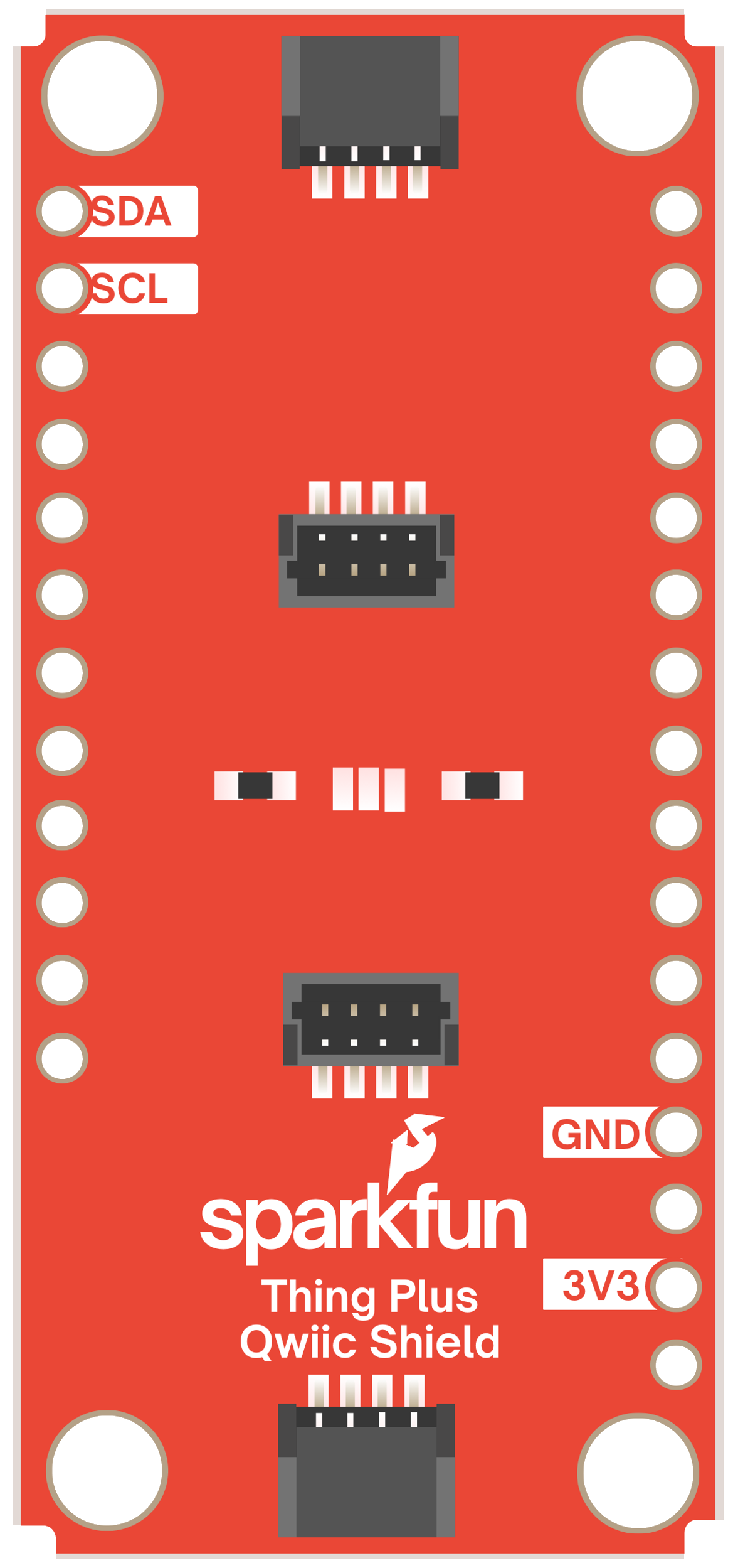
The Qwiic Shield (Thing Plus) by SparkFun is a versatile add-on board designed to expand the functionality of the Thing Plus microcontroller. It features multiple Qwiic connectors, enabling seamless integration of I2C sensors and devices. This shield simplifies rapid prototyping and development by eliminating the need for soldering or complex wiring, making it ideal for both beginners and experienced developers.
Explore Projects Built with Qwiic Shield (Thing Plus)
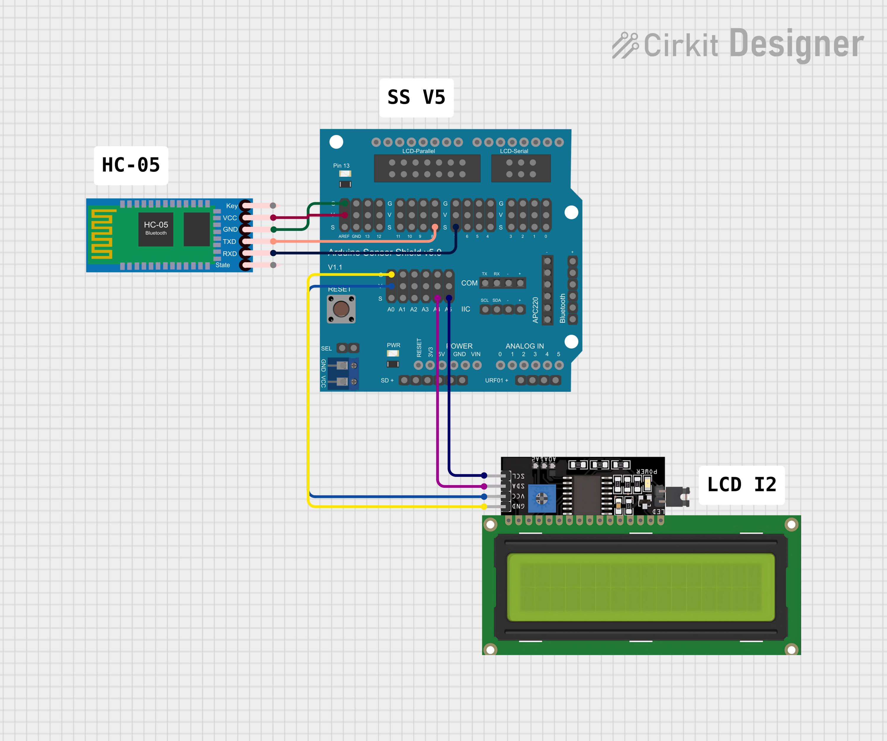

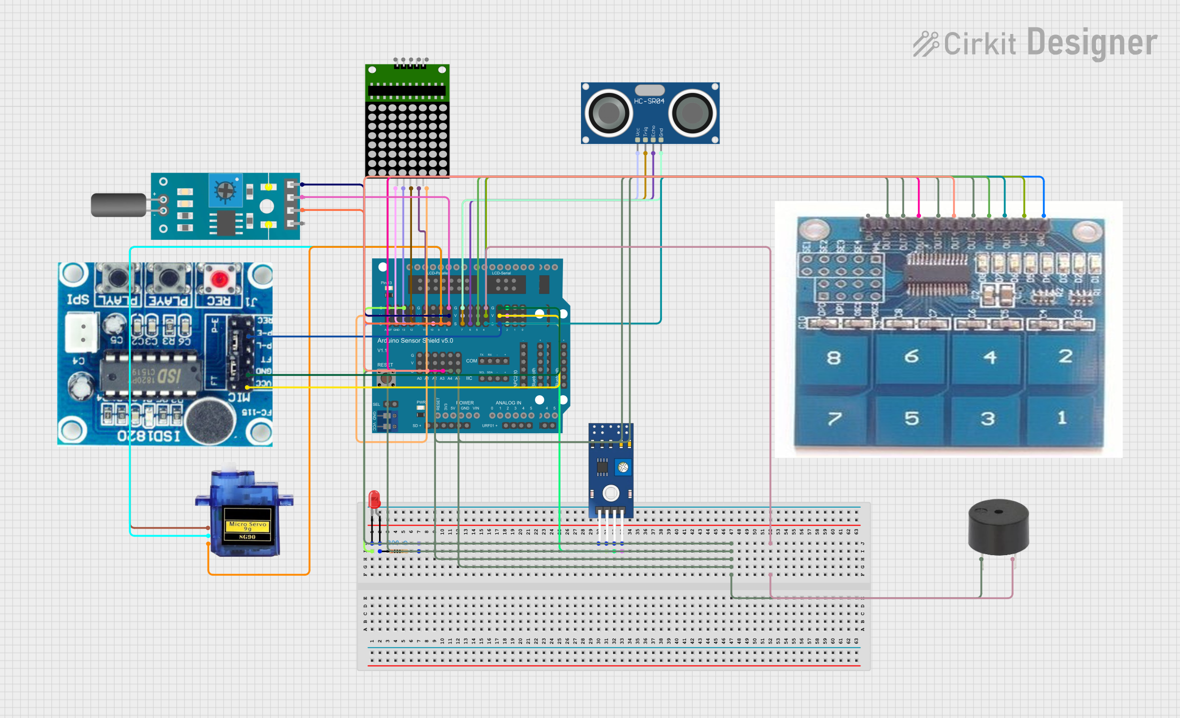
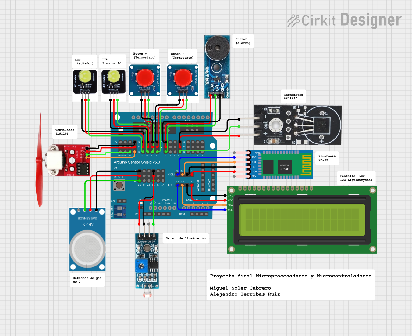
Explore Projects Built with Qwiic Shield (Thing Plus)
Common Applications and Use Cases
- Rapid prototyping of IoT devices
- Integration of multiple I2C sensors and modules
- Educational projects and workshops
- Development of smart devices and automation systems
- Testing and debugging I2C-based components
Technical Specifications
The Qwiic Shield (Thing Plus) is designed to work seamlessly with SparkFun's Thing Plus microcontroller boards. Below are the key technical details:
Key Specifications
| Parameter | Value |
|---|---|
| Microcontroller Compatibility | SparkFun Thing Plus (ESP32, RP2040, etc.) |
| I2C Interface | Qwiic Connect System (4-pin JST connector) |
| Number of Qwiic Ports | 4 |
| Input Voltage | 3.3V (from Thing Plus board) |
| Dimensions | 2.5" x 1.0" (63.5mm x 25.4mm) |
| Weight | ~5g |
Pin Configuration and Descriptions
The Qwiic Shield connects directly to the Thing Plus microcontroller via its headers. Below is the pin configuration for the Qwiic connectors:
| Pin Name | Description |
|---|---|
| GND | Ground |
| 3.3V | Power supply (3.3V) |
| SDA | I2C Data Line |
| SCL | I2C Clock Line |
Usage Instructions
The Qwiic Shield (Thing Plus) is designed for plug-and-play functionality, making it easy to connect and use I2C devices. Follow the steps below to get started:
Step 1: Hardware Setup
- Attach the Shield: Align the Qwiic Shield with the Thing Plus microcontroller and press it firmly into the headers.
- Connect I2C Devices: Use Qwiic cables to connect your I2C sensors or modules to any of the four Qwiic connectors on the shield.
- Power the Board: Supply power to the Thing Plus microcontroller via USB or an external power source.
Step 2: Software Setup
- Install Arduino IDE: Download and install the Arduino IDE if you haven’t already.
- Install Required Libraries: Many Qwiic-compatible devices require specific libraries. For example:
- Open the Arduino IDE.
- Go to Sketch > Include Library > Manage Libraries.
- Search for the library corresponding to your I2C device (e.g., "SparkFun Qwiic Sensor").
- Click Install.
Step 3: Example Code
Below is an example of how to use the Qwiic Shield with a Qwiic-compatible temperature sensor (e.g., SparkFun TMP102):
#include <Wire.h> // Include the Wire library for I2C communication
#include <SparkFun_TMP102.h> // Include the TMP102 library

TMP102 tempSensor; // Create an instance of the TMP102 class

void setup() {
  Serial.begin(9600); // Initialize serial communication
  Wire.begin(); // Initialize I2C communication

  if (!tempSensor.begin()) {
    // Check if the sensor is connected
    Serial.println("TMP102 not detected. Check connections.");
    while (1); // Halt the program if the sensor is not found
  }

  Serial.println("TMP102 detected. Starting temperature readings...");
}

void loop() {
  float temperature = tempSensor.readTempC(); // Read temperature in Celsius
  Serial.print("Temperature: ");
  Serial.print(temperature);
  Serial.println(" °C");

  delay(1000); // Wait 1 second before the next reading
}
Important Considerations and Best Practices
- Power Supply: Ensure the Thing Plus board is powered with 3.3V. Avoid connecting 5V devices directly to the Qwiic Shield.
- Cable Length: Keep Qwiic cable lengths short to maintain signal integrity, especially when using multiple devices.
- Address Conflicts: If using multiple I2C devices, ensure they have unique I2C addresses. Some devices allow address modification via solder jumpers.
Troubleshooting and FAQs
Common Issues and Solutions
Qwiic Device Not Detected
- Cause: Loose connections or incorrect wiring.
- Solution: Ensure all Qwiic cables are securely connected. Verify that the Thing Plus board is powered.
I2C Address Conflict
- Cause: Two devices on the same I2C bus have the same address.
- Solution: Check the datasheets of your devices and modify the address of one device if possible.
No Data from Sensor
- Cause: Missing or incorrect library.
- Solution: Verify that the correct library is installed and included in your code.
Intermittent Communication Issues
- Cause: Excessive cable length or electrical noise.
- Solution: Use shorter Qwiic cables and ensure a clean power supply.
FAQs
Q: Can I use the Qwiic Shield with non-SparkFun I2C devices?
A: Yes, as long as the device uses the I2C protocol and operates at 3.3V. You may need to use a Qwiic adapter for non-Qwiic devices.
Q: How many devices can I connect to the Qwiic Shield?
A: The I2C bus supports multiple devices, but the total number depends on the power requirements and address availability of the devices.
Q: Can I stack multiple Qwiic Shields?
A: No, the Qwiic Shield is designed to be used as a single layer on top of the Thing Plus microcontroller.
Q: Is the Qwiic Shield compatible with 5V microcontrollers?
A: No, the Qwiic Shield is designed for 3.3V microcontrollers like the Thing Plus series. Using it with 5V microcontrollers may damage the shield or connected devices.