
How to Use ENCODER N20: Examples, Pinouts, and Specs
 Design with ENCODER N20 in Cirkit Designer
Introduction
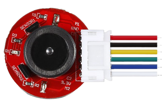
The ENCODER N20 is a small, high-precision rotary encoder designed to measure the position or rotation of a shaft. Its compact design makes it ideal for applications where space is limited. This encoder is commonly used in robotics, automation systems, and various electronic projects requiring accurate rotational feedback. It is often paired with DC motors to provide precise control over motor position and speed.
Explore Projects Built with ENCODER N20
 Open Project in Cirkit Designer
 Open Project in Cirkit Designer
 Open Project in Cirkit Designer
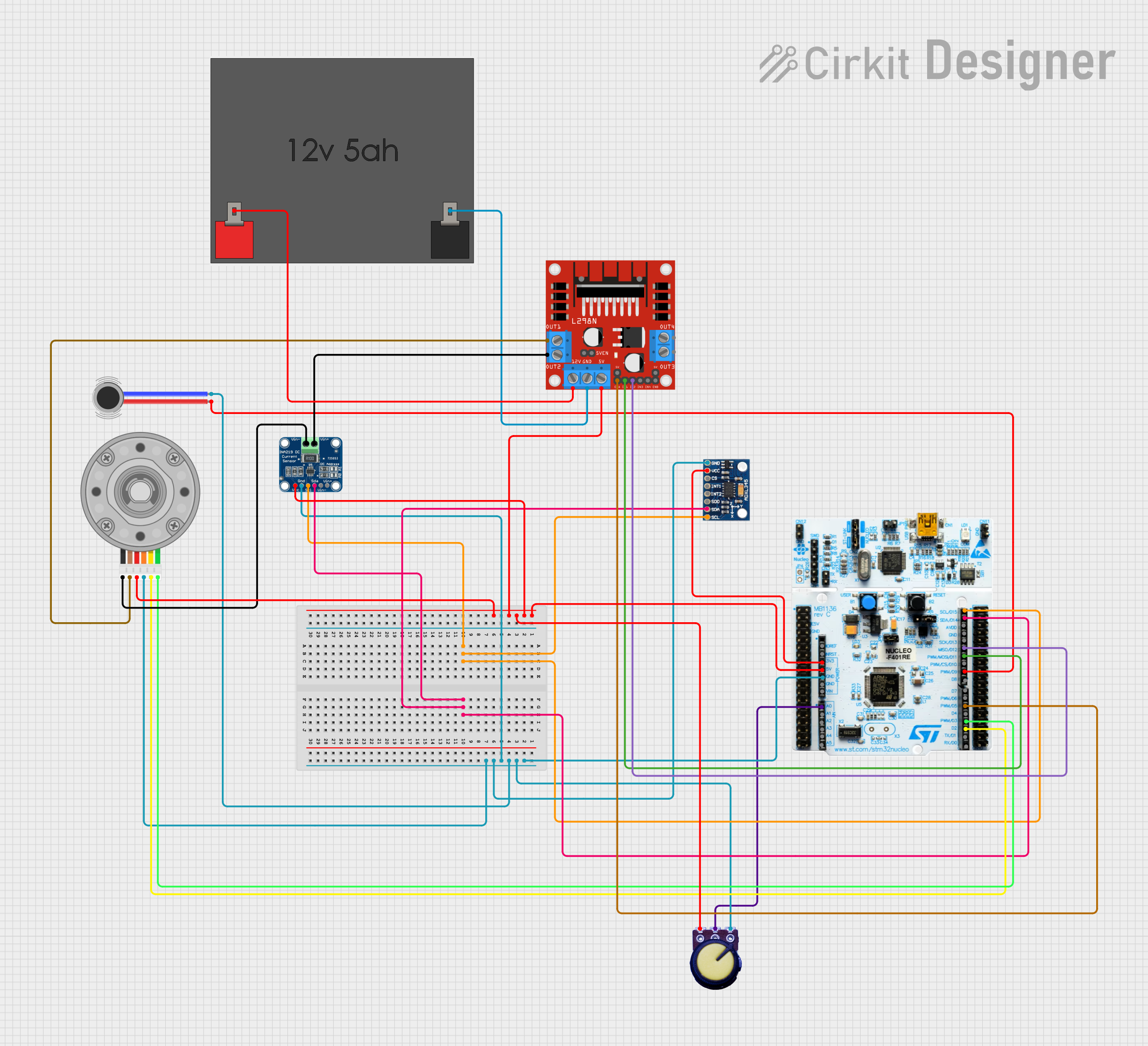 Open Project in Cirkit Designer
Explore Projects Built with ENCODER N20
Open Project in Cirkit DesignerOpen Project in Cirkit DesignerOpen Project in Cirkit DesignerOpen Project in Cirkit DesignerCommon Applications
- Robotics for motor position and speed feedback
- Automation systems for precise rotational measurements
- DIY electronics projects involving motion control
- Servo mechanisms and closed-loop control systems
Technical Specifications
The ENCODER N20 is designed to provide reliable and accurate feedback in a small form factor. Below are its key technical details:
Key Specifications
| Parameter | Value |
|---|---|
| Operating Voltage | 3.3V to 5V |
| Output Signal Type | Quadrature (A and B channels) |
| Resolution | 11 pulses per revolution (PPR) |
| Maximum RPM | 10,000 RPM |
| Output Signal Voltage | Same as input voltage |
| Operating Temperature | -20°C to 85°C |
| Dimensions | 12mm x 10mm x 10mm |
Pin Configuration
The ENCODER N20 typically has four pins for interfacing. The table below describes each pin:
| Pin Number | Pin Name | Description |
|---|---|---|
| 1 | VCC | Power supply input (3.3V to 5V) |
| 2 | GND | Ground connection |
| 3 | A | Channel A output signal (quadrature signal) |
| 4 | B | Channel B output signal (quadrature signal) |
Usage Instructions
The ENCODER N20 is straightforward to use in a circuit. Below are the steps and considerations for integrating it into your project:
Connecting the ENCODER N20
- Power Supply: Connect the VCC pin to a 3.3V or 5V power source and the GND pin to the ground.
- Signal Pins: Connect the A and B pins to the input pins of a microcontroller or an encoder interface circuit.
- Pull-Up Resistors: If the encoder outputs are open-drain, use pull-up resistors (typically 10kΩ) on the A and B pins to ensure proper signal levels.
Example Circuit with Arduino UNO
Below is an example of how to connect the ENCODER N20 to an Arduino UNO:
- VCC: Connect to the Arduino's 5V pin.
- GND: Connect to the Arduino's GND pin.
- A: Connect to Arduino digital pin 2.
- B: Connect to Arduino digital pin 3.
Sample Arduino Code
The following code demonstrates how to read the encoder's signals and calculate the position:
// ENCODER N20 Example Code for Arduino UNO
// This code reads the quadrature signals from the encoder and calculates position.

#define ENCODER_PIN_A 2  // Channel A connected to digital pin 2
#define ENCODER_PIN_B 3  // Channel B connected to digital pin 3

volatile int encoderPosition = 0;  // Variable to store the encoder position
volatile int lastEncoded = 0;      // Last encoded value

void setup() {
  pinMode(ENCODER_PIN_A, INPUT);  // Set pin A as input
  pinMode(ENCODER_PIN_B, INPUT);  // Set pin B as input

  // Enable interrupts for pin A and pin B
  attachInterrupt(digitalPinToInterrupt(ENCODER_PIN_A), updateEncoder, CHANGE);
  attachInterrupt(digitalPinToInterrupt(ENCODER_PIN_B), updateEncoder, CHANGE);

  Serial.begin(9600);  // Initialize serial communication
}

void loop() {
  // Print the encoder position to the Serial Monitor
  Serial.print("Encoder Position: ");
  Serial.println(encoderPosition);
  delay(100);  // Delay for readability
}

void updateEncoder() {
  // Read the current state of the encoder pins
  int MSB = digitalRead(ENCODER_PIN_A);  // Most significant bit
  int LSB = digitalRead(ENCODER_PIN_B);  // Least significant bit

  int encoded = (MSB << 1) | LSB;  // Combine the two bits into a single value
  int sum = (lastEncoded << 2) | encoded;  // Combine with the last encoded value

  // Determine the direction of rotation
  if (sum == 0b1101 || sum == 0b0100 || sum == 0b0010 || sum == 0b1011) {
    encoderPosition++;  // Clockwise rotation
  } else if (sum == 0b1110 || sum == 0b0111 || sum == 0b0001 || sum == 0b1000) {
    encoderPosition--;  // Counterclockwise rotation
  }

  lastEncoded = encoded;  // Update the last encoded value
}
Best Practices
- Use shielded cables for the encoder signals to minimize noise interference.
- Avoid exceeding the maximum RPM to ensure accurate readings.
- Ensure proper alignment of the encoder with the motor shaft to prevent mechanical stress.
Troubleshooting and FAQs
Common Issues
No Output Signal:
- Cause: Incorrect wiring or insufficient power supply.
- Solution: Verify all connections and ensure the power supply voltage is within the specified range.
Inconsistent Readings:
- Cause: Electrical noise or loose connections.
- Solution: Use shielded cables and secure all connections. Add pull-up resistors if necessary.
Incorrect Direction Detection:
- Cause: A and B channels are swapped.
- Solution: Swap the connections of the A and B pins.
Position Drift:
- Cause: High-speed operation or missed pulses.
- Solution: Reduce the RPM or use a microcontroller with higher interrupt handling capability.
FAQs
Q1: Can the ENCODER N20 be used with a 3.3V microcontroller?
Yes, the ENCODER N20 operates within a voltage range of 3.3V to 5V, making it compatible with 3.3V microcontrollers.
Q2: What is the purpose of the quadrature signals?
Quadrature signals allow the encoder to determine both the position and direction of rotation.
Q3: How do I calculate the resolution in degrees?
The resolution in degrees is calculated as ( \text{Resolution} = \frac{360}{\text{PPR}} ). For the ENCODER N20, this is approximately 32.73° per pulse.
Q4: Can I use the ENCODER N20 for speed measurement?
Yes, by measuring the frequency of the pulses, you can calculate the rotational speed of the shaft.
This concludes the documentation for the ENCODER N20.