Cirkit Designer Logo
Cirkit Designer
Your all-in-one circuit design IDE
Home / 
Component Documentation

How to Use PCA9515A: Examples, Pinouts, and Specs

Image of PCA9515A
Cirkit Designer LogoDesign with PCA9515A in Cirkit Designer

Introduction

The PCA9515A is a dual bidirectional I2C bus buffer designed to extend I2C bus signals over longer distances while maintaining signal integrity. It supports both standard-mode (up to 100 kHz) and fast-mode (up to 400 kHz) I2C communication. The device is particularly useful in applications where multiple I2C masters and slaves are connected, as it isolates capacitance and ensures reliable communication.

Explore Projects Built with PCA9515A

Use Cirkit Designer to design, explore, and prototype these projects online. Some projects support real-time simulation. Click "Open Project" to start designing instantly!
Battery-Powered Raspberry Pi Pico GPS Tracker with Sensor Integration
Image of Copy of CanSet v1: A project utilizing PCA9515A in a practical application
This circuit is a data acquisition and communication system powered by a LiPoly battery and managed by a Raspberry Pi Pico. It includes sensors (BMP280, MPU9250) for environmental data, a GPS module for location tracking, an SD card for data storage, and a WLR089-CanSAT for wireless communication. The TP4056 module handles battery charging, and a toggle switch controls power distribution.
Cirkit Designer LogoOpen Project in Cirkit Designer
Raspberry Pi 4B-Controlled Biometric Access System with Dual Stepper Motor Actuation
Image of wiring: A project utilizing PCA9515A in a practical application
This circuit features a Raspberry Pi 4B as the central controller, interfacing with various sensors and modules. It includes a vl53l0xv2 time-of-flight sensor and an AS5600 magnetic encoder for position sensing, both connected via I2C (SDA/SCL lines). The circuit also controls two DRV8825 stepper motor drivers connected to NEMA 17 stepper motors, receives temperature data from a DS18B20 sensor, and communicates with a fingerprint scanner for biometric input. A TM1637 display module is included for user feedback. Power management is handled by a buck converter and a 12V power supply, with the Raspberry Pi and other 3.3V components powered through the buck converter's regulated output.
Cirkit Designer LogoOpen Project in Cirkit Designer
Arduino UNO and PCA9685 Controlled Robotic Arm with Bluetooth and Audio Feedback
Image of spiderbot: A project utilizing PCA9515A in a practical application
This circuit is a multi-functional robotic control system powered by an Arduino UNO, which interfaces with a PCA9685 PWM driver to control multiple servos, an L298N motor driver to control two DC motors, and a DFPlayer Mini for audio playback. The system is designed to be controlled via Bluetooth using an HC-05 module, allowing for remote operation of servos, motors, and audio playback.
Cirkit Designer LogoOpen Project in Cirkit Designer
Arduino Mega 2560 Based Security System with Fingerprint Authentication and SMS Alerts
Image of Door security system: A project utilizing PCA9515A in a practical application
This circuit features an Arduino Mega 2560 microcontroller interfaced with a SIM800L GSM module, two fingerprint scanners, an I2C LCD display, an IR sensor, and a piezo buzzer. Power management is handled by a PowerBoost 1000 Basic Pad USB, a TP4056 charging module, and a Li-ion 18650 battery, with an option to use a Mini AC-DC 110V-230V to 5V 700mA module for direct power supply. The primary functionality appears to be a security system with GSM communication capabilities, biometric access control, and visual/audible feedback.
Cirkit Designer LogoOpen Project in Cirkit Designer

Explore Projects Built with PCA9515A

Use Cirkit Designer to design, explore, and prototype these projects online. Some projects support real-time simulation. Click "Open Project" to start designing instantly!
Image of Copy of CanSet v1: A project utilizing PCA9515A in a practical application
Battery-Powered Raspberry Pi Pico GPS Tracker with Sensor Integration
This circuit is a data acquisition and communication system powered by a LiPoly battery and managed by a Raspberry Pi Pico. It includes sensors (BMP280, MPU9250) for environmental data, a GPS module for location tracking, an SD card for data storage, and a WLR089-CanSAT for wireless communication. The TP4056 module handles battery charging, and a toggle switch controls power distribution.
Cirkit Designer LogoOpen Project in Cirkit Designer
Image of wiring: A project utilizing PCA9515A in a practical application
Raspberry Pi 4B-Controlled Biometric Access System with Dual Stepper Motor Actuation
This circuit features a Raspberry Pi 4B as the central controller, interfacing with various sensors and modules. It includes a vl53l0xv2 time-of-flight sensor and an AS5600 magnetic encoder for position sensing, both connected via I2C (SDA/SCL lines). The circuit also controls two DRV8825 stepper motor drivers connected to NEMA 17 stepper motors, receives temperature data from a DS18B20 sensor, and communicates with a fingerprint scanner for biometric input. A TM1637 display module is included for user feedback. Power management is handled by a buck converter and a 12V power supply, with the Raspberry Pi and other 3.3V components powered through the buck converter's regulated output.
Cirkit Designer LogoOpen Project in Cirkit Designer
Image of spiderbot: A project utilizing PCA9515A in a practical application
Arduino UNO and PCA9685 Controlled Robotic Arm with Bluetooth and Audio Feedback
This circuit is a multi-functional robotic control system powered by an Arduino UNO, which interfaces with a PCA9685 PWM driver to control multiple servos, an L298N motor driver to control two DC motors, and a DFPlayer Mini for audio playback. The system is designed to be controlled via Bluetooth using an HC-05 module, allowing for remote operation of servos, motors, and audio playback.
Cirkit Designer LogoOpen Project in Cirkit Designer
Image of Door security system: A project utilizing PCA9515A in a practical application
Arduino Mega 2560 Based Security System with Fingerprint Authentication and SMS Alerts
This circuit features an Arduino Mega 2560 microcontroller interfaced with a SIM800L GSM module, two fingerprint scanners, an I2C LCD display, an IR sensor, and a piezo buzzer. Power management is handled by a PowerBoost 1000 Basic Pad USB, a TP4056 charging module, and a Li-ion 18650 battery, with an option to use a Mini AC-DC 110V-230V to 5V 700mA module for direct power supply. The primary functionality appears to be a security system with GSM communication capabilities, biometric access control, and visual/audible feedback.
Cirkit Designer LogoOpen Project in Cirkit Designer

Common Applications and Use Cases

  • Extending I2C bus signals in large systems
  • Multi-master and multi-slave I2C configurations
  • Industrial control systems
  • Consumer electronics with long I2C wiring
  • Signal integrity improvement in high-capacitance environments

Technical Specifications

Key Technical Details

  • Supply Voltage (Vcc): 2.3 V to 3.6 V
  • I2C Bus Speed: Standard-mode (100 kHz) and Fast-mode (400 kHz)
  • Operating Temperature Range: -40°C to +85°C
  • Low Standby Current: 1 µA (typical)
  • Propagation Delay: 0.5 ns (typical)
  • Capacitance Isolation: Supports up to 400 pF on each side of the buffer
  • ESD Protection: ±4 kV (HBM)

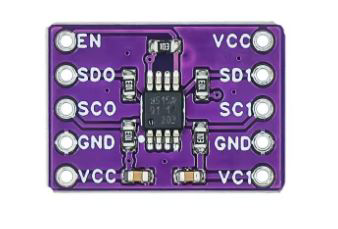
Pin Configuration and Descriptions

The PCA9515A is available in an 8-pin SOIC package. Below is the pinout and description:

Pin Number Pin Name Description
1 VCC Power supply input (2.3 V to 3.6 V).
2 A0 I2C bus A, data line (SDA).
3 A1 I2C bus A, clock line (SCL).
4 GND Ground.
5 B0 I2C bus B, data line (SDA).
6 B1 I2C bus B, clock line (SCL).
7 EN Enable pin. High to enable the buffer, low to disable.
8 NC No connection.

Usage Instructions

How to Use the PCA9515A in a Circuit

  1. Power Supply:

    • Connect the VCC pin to a 2.3 V to 3.6 V power source.
    • Connect the GND pin to the ground of the circuit.
  2. I2C Bus Connections:

    • Connect the SDA and SCL lines of the first I2C bus to pins A0 and A1, respectively.
    • Connect the SDA and SCL lines of the second I2C bus to pins B0 and B1, respectively.
  3. Enable Pin:

    • Drive the EN pin high to enable the buffer. If the EN pin is low, the buffer is disabled, and the A and B sides are isolated.
  4. Pull-Up Resistors:

    • Ensure that each side of the I2C bus (A and B) has appropriate pull-up resistors. The PCA9515A does not provide internal pull-ups.
  5. Capacitance Considerations:

    • The PCA9515A isolates the capacitance of the A and B sides, allowing up to 400 pF on each side. Ensure that the total capacitance on each bus does not exceed this limit.

Important Considerations and Best Practices

  • Avoid connecting multiple PCA9515A devices in series, as this may cause signal integrity issues.
  • Ensure that the EN pin is properly controlled to avoid unintentional isolation of the I2C buses.
  • Use proper decoupling capacitors (e.g., 0.1 µF) near the VCC pin to stabilize the power supply.
  • Verify that the I2C devices connected to the A and B sides operate within the same voltage range as the PCA9515A.

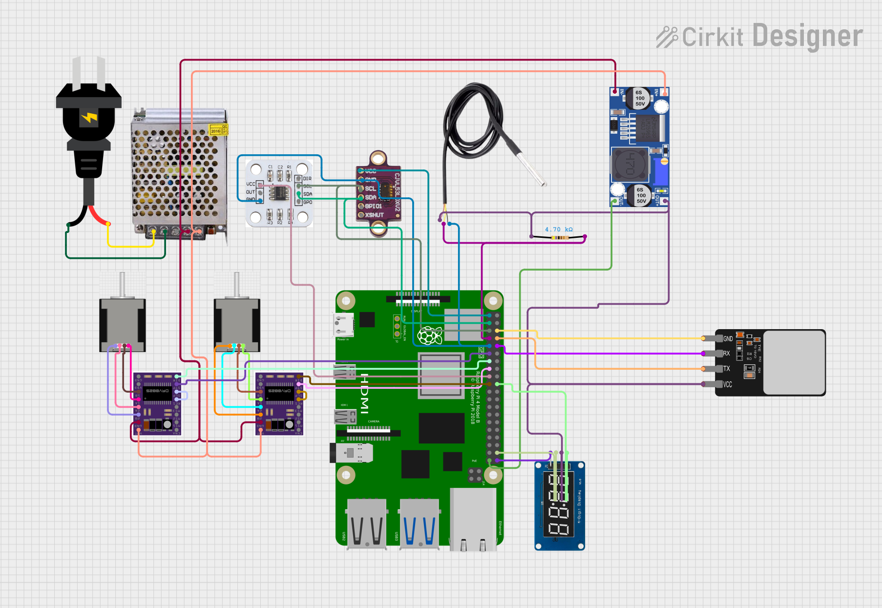
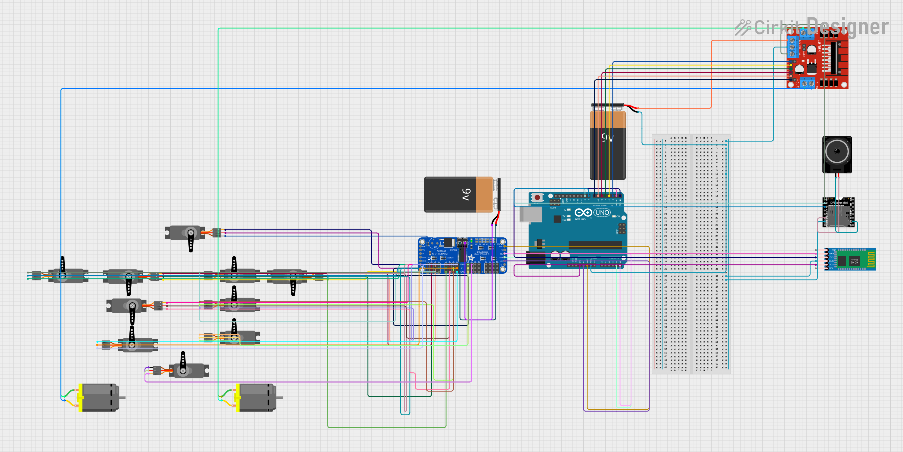
Example: Connecting PCA9515A to an Arduino UNO

Below is an example of how to use the PCA9515A to extend an I2C bus with an Arduino UNO:

Circuit Diagram

  • Connect the Arduino's SDA (A4) and SCL (A5) pins to the A0 and A1 pins of the PCA9515A.
  • Connect the B0 and B1 pins to the extended I2C bus.
  • Use pull-up resistors (e.g., 4.7 kΩ) on both sides of the buffer.

Arduino Code

#include <Wire.h> // Include the Wire library for I2C communication

void setup() {
  Wire.begin(); // Initialize the I2C bus
  Serial.begin(9600); // Start serial communication for debugging
  Serial.println("PCA9515A I2C Bus Buffer Example");
}

void loop() {
  Wire.beginTransmission(0x50); // Start communication with a slave device
  Wire.write(0x00); // Send a command or data
  if (Wire.endTransmission() == 0) {
    Serial.println("Data sent successfully!");
  } else {
    Serial.println("Error: Failed to communicate with the device.");
  }
  delay(1000); // Wait for 1 second before repeating
}

Troubleshooting and FAQs

Common Issues and Solutions

  1. No Communication on the I2C Bus:

    • Cause: The EN pin is not driven high.
    • Solution: Ensure the EN pin is connected to a high logic level (e.g., VCC).
  2. Signal Distortion or Noise:

    • Cause: Missing or incorrect pull-up resistors.
    • Solution: Verify that appropriate pull-up resistors (e.g., 4.7 kΩ) are present on both sides of the buffer.
  3. I2C Bus Not Extending Properly:

    • Cause: Excessive capacitance on one or both sides of the buffer.
    • Solution: Measure the capacitance and ensure it does not exceed 400 pF on either side.
  4. Device Overheating:

    • Cause: Incorrect power supply voltage.
    • Solution: Verify that the VCC pin is supplied with a voltage between 2.3 V and 3.6 V.

FAQs

Q1: Can I use the PCA9515A with 5V I2C devices?
A1: No, the PCA9515A operates at a maximum voltage of 3.6 V. Use level shifters if interfacing with 5V devices.

Q2: How many PCA9515A devices can I use in a single system?
A2: You can use multiple PCA9515A devices, but avoid connecting them in series to prevent signal integrity issues.

Q3: Do I need pull-up resistors on both sides of the buffer?
A3: Yes, each side of the I2C bus requires its own pull-up resistors, as the PCA9515A does not provide internal pull-ups.