Cirkit Designer
Your all-in-one circuit design IDE
Home /
Component Documentation
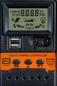
How to Use SCC: Examples, Pinouts, and Specs
Introduction
The Switched Capacitor Circuit (SCC) is a versatile electronic component used to implement various analog functions such as filters, oscillators, and more. By switching capacitors in and out of the circuit at a high frequency, the SCC can effectively simulate resistors and other analog components, making it a valuable tool in both analog and digital circuit design.
Explore Projects Built with SCC
Solar-Powered Battery Charging System with MPPT and ESP32
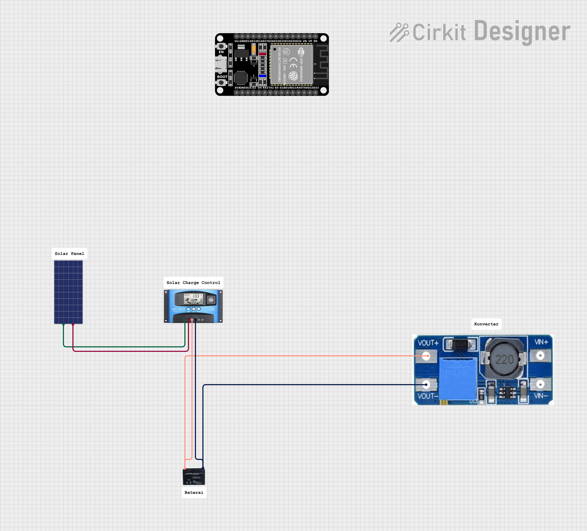
This circuit is a solar-powered battery charging system with an MPPT (Maximum Power Point Tracking) charge controller. The solar panel provides power to the MPPT SCC, which optimizes the charging of a 12V battery. A step-up boost converter is used to regulate the output voltage from the battery.
ESP32-Based Solar-Powered Environmental Monitoring and Water Management System
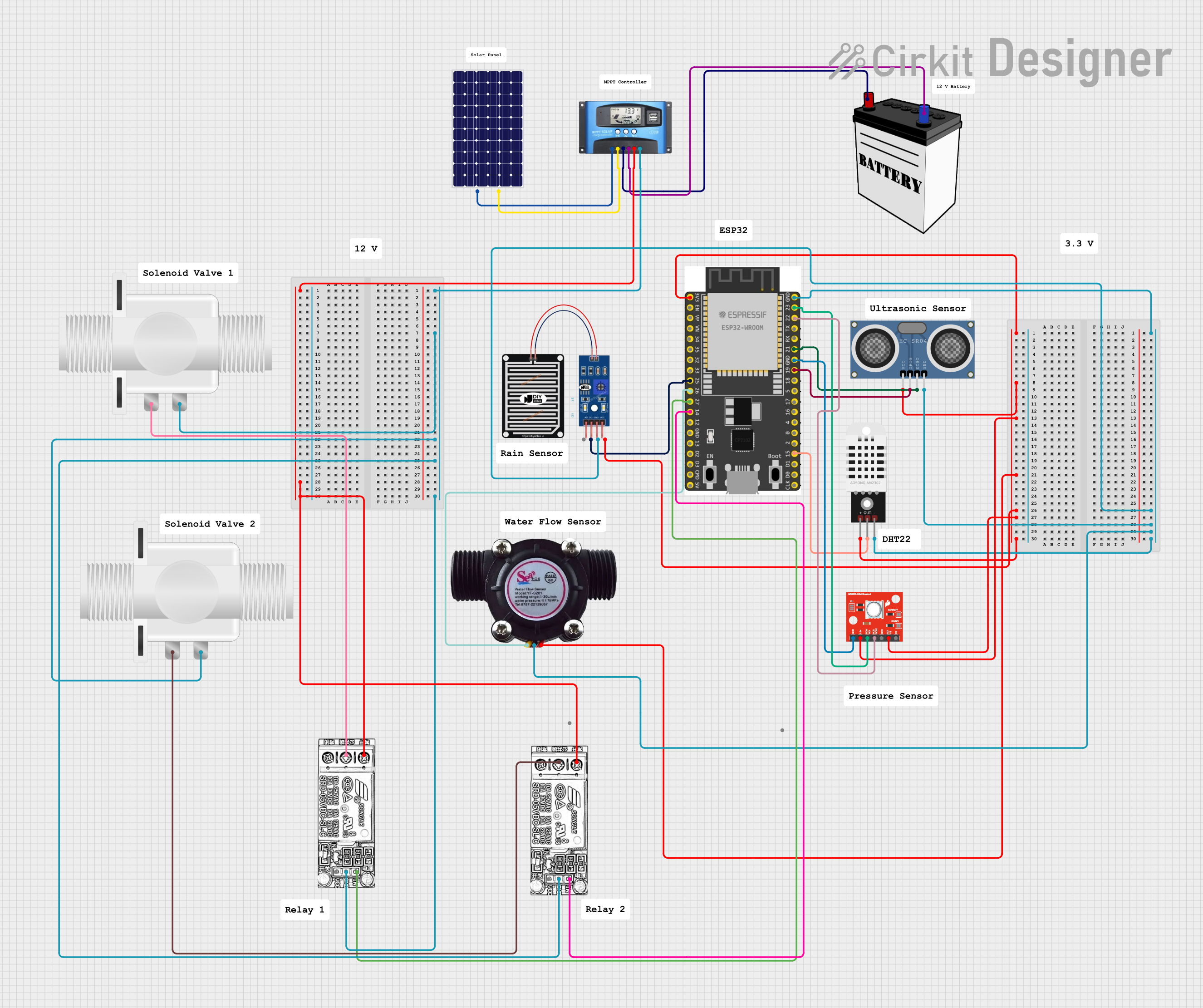
This is a solar-powered environmental monitoring and water flow control system. It uses an ESP32 microcontroller to process data from multiple sensors and manage water flow through solenoid valves, with power regulation handled by an MPPT Solar Charge Controller connected to a solar panel and a 12V battery.
Solar-Powered Battery Charging System with MPPT and Voltage Regulation
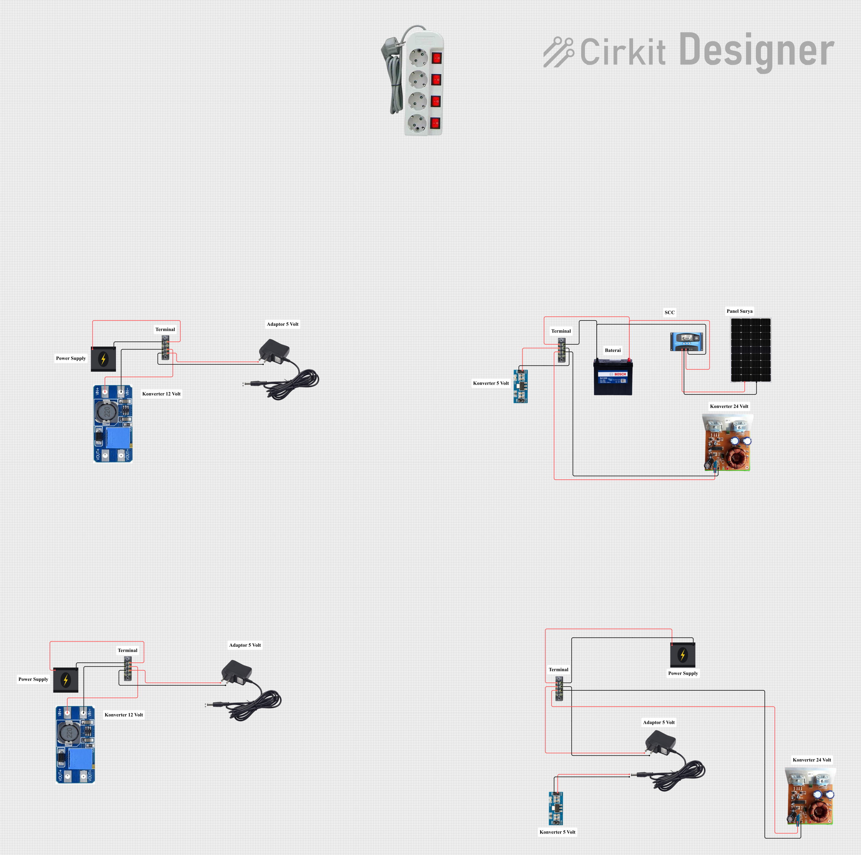
This circuit is a solar power management system that includes a solar panel, an MPPT solar charge controller, a 12V 200Ah battery, and various voltage converters. The system is designed to harness solar energy, store it in a battery, and provide regulated power outputs at different voltages for various loads.
PID Temperature Control System with Thermocouple and SSR

This circuit is a temperature control system that uses a thermocouple to measure temperature and a PID controller to regulate it. The PID controller drives a solid-state relay (SSR) to control an external load, with power supplied through an AC inlet socket.
Explore Projects Built with SCC
Solar-Powered Battery Charging System with MPPT and ESP32
This circuit is a solar-powered battery charging system with an MPPT (Maximum Power Point Tracking) charge controller. The solar panel provides power to the MPPT SCC, which optimizes the charging of a 12V battery. A step-up boost converter is used to regulate the output voltage from the battery.
ESP32-Based Solar-Powered Environmental Monitoring and Water Management System
This is a solar-powered environmental monitoring and water flow control system. It uses an ESP32 microcontroller to process data from multiple sensors and manage water flow through solenoid valves, with power regulation handled by an MPPT Solar Charge Controller connected to a solar panel and a 12V battery.
Solar-Powered Battery Charging System with MPPT and Voltage Regulation
This circuit is a solar power management system that includes a solar panel, an MPPT solar charge controller, a 12V 200Ah battery, and various voltage converters. The system is designed to harness solar energy, store it in a battery, and provide regulated power outputs at different voltages for various loads.
PID Temperature Control System with Thermocouple and SSR
This circuit is a temperature control system that uses a thermocouple to measure temperature and a PID controller to regulate it. The PID controller drives a solid-state relay (SSR) to control an external load, with power supplied through an AC inlet socket.
Common Applications and Use Cases
- Filters: Low-pass, high-pass, band-pass, and band-stop filters.
- Oscillators: Generation of stable and precise oscillation frequencies.
- Analog Signal Processing: Amplification, integration, and differentiation of analog signals.
- Data Conversion: Analog-to-digital and digital-to-analog conversion.
Technical Specifications
Key Technical Details
| Parameter | Value |
|---|---|
| Supply Voltage | 3.3V to 5V |
| Operating Current | 1mA to 10mA |
| Switching Frequency | Up to 1MHz |
| Temperature Range | -40°C to +85°C |
| Package Type | DIP, SMD |
Pin Configuration and Descriptions
| Pin Number | Pin Name | Description |
|---|---|---|
| 1 | VCC | Supply Voltage (3.3V to 5V) |
| 2 | GND | Ground |
| 3 | IN | Input Signal |
| 4 | OUT | Output Signal |
| 5 | CLK | Clock Input for Switching Frequency |
| 6 | NC | No Connection |
| 7 | NC | No Connection |
| 8 | VEE | Negative Supply Voltage (Optional, for dual supply) |
Usage Instructions
How to Use the SCC in a Circuit
- Power Supply: Connect the VCC pin to a 3.3V to 5V power supply and the GND pin to ground.
- Input Signal: Connect the input signal to the IN pin.
- Output Signal: The processed signal will be available at the OUT pin.
- Clock Input: Provide a clock signal to the CLK pin to control the switching frequency of the capacitors.
Important Considerations and Best Practices
- Clock Frequency: Ensure that the clock frequency is within the specified range (up to 1MHz) for optimal performance.
- Power Supply: Use a stable power supply to avoid noise and fluctuations in the output signal.
- Bypass Capacitors: Place bypass capacitors (e.g., 0.1µF) close to the VCC and GND pins to filter out power supply noise.
- Thermal Management: Ensure adequate cooling if the SCC is used in high-frequency or high-current applications.
Example Circuit with Arduino UNO
/*
 * Example code to use SCC with Arduino UNO
 * This code generates a clock signal for the SCC
 * and reads the output signal.
 */

const int clkPin = 9;  // Pin connected to SCC CLK
const int inPin = A0;  // Pin connected to SCC IN
const int outPin = A1; // Pin connected to SCC OUT

void setup() {
  pinMode(clkPin, OUTPUT);
  pinMode(inPin, INPUT);
  pinMode(outPin, INPUT);
  Serial.begin(9600);
}

void loop() {
  // Generate a clock signal
  digitalWrite(clkPin, HIGH);
  delayMicroseconds(1); // Adjust for desired frequency
  digitalWrite(clkPin, LOW);
  delayMicroseconds(1); // Adjust for desired frequency

  // Read the input and output signals
  int inputSignal = analogRead(inPin);
  int outputSignal = analogRead(outPin);

  // Print the signals to the Serial Monitor
  Serial.print("Input Signal: ");
  Serial.print(inputSignal);
  Serial.print(" Output Signal: ");
  Serial.println(outputSignal);

  delay(100); // Adjust as needed
}
Troubleshooting and FAQs
Common Issues Users Might Face
No Output Signal:
- Solution: Check the power supply connections and ensure the clock signal is being provided to the CLK pin.
Noisy Output Signal:
- Solution: Use bypass capacitors close to the VCC and GND pins to filter out power supply noise.
Incorrect Frequency Response:
- Solution: Verify the clock frequency and ensure it is within the specified range.
Solutions and Tips for Troubleshooting
- Check Connections: Ensure all connections are secure and correct according to the pin configuration.
- Verify Power Supply: Use a stable and clean power supply to avoid noise and fluctuations.
- Use Proper Clock Source: Ensure the clock source provides a stable and accurate frequency.
- Consult Datasheet: Refer to the manufacturer's datasheet for detailed specifications and application notes.
By following this documentation, users can effectively utilize the SCC in their electronic projects, whether they are beginners or experienced engineers.