Cirkit Designer Logo
Cirkit Designer
Your all-in-one circuit design IDE
Home / 
Component Documentation

How to Use Logic level 3,3V-5V step-up (4 channels, SPI/UART): Examples, Pinouts, and Specs

Image of Logic level 3,3V-5V step-up (4 channels, SPI/UART)
Cirkit Designer LogoDesign with Logic level 3,3V-5V step-up (4 channels, SPI/UART) in Cirkit Designer

Introduction

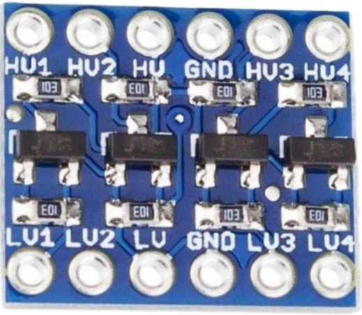
The Logic Level 3.3V-5V Step-Up (4 Channels, SPI/UART), manufactured by JH Global Trading (HK) Co., Limited, is a versatile bidirectional logic level converter. It allows seamless communication between devices operating at different voltage levels, such as 3.3V and 5V. This component is particularly useful in interfacing microcontrollers, sensors, and communication modules that require different logic levels.

Explore Projects Built with Logic level 3,3V-5V step-up (4 channels, SPI/UART)

Use Cirkit Designer to design, explore, and prototype these projects online. Some projects support real-time simulation. Click "Open Project" to start designing instantly!
Wi-Fi Controlled Device Interface with Wemos D1 Mini and Logic Level Converter
Image of Toshiba AC D1 mini: A project utilizing Logic level 3,3V-5V step-up (4 channels, SPI/UART) in a practical application
This circuit features a Wemos D1 Mini microcontroller interfaced with a Bi-Directional Logic Level Converter to facilitate communication with a 5V RX/TX module. The level converter ensures proper voltage translation between the 3.3V logic of the Wemos D1 Mini and the 5V logic of the RX/TX module.
Cirkit Designer LogoOpen Project in Cirkit Designer
Battery-Powered 18650 Li-ion Charger with USB Output and Adjustable Voltage Regulator
Image of Breadboard: A project utilizing Logic level 3,3V-5V step-up (4 channels, SPI/UART) in a practical application
This circuit is a battery management and power supply system that uses three 3.7V batteries connected to a 3S 10A Li-ion 18650 Charger Protection Board Module for balanced charging and protection. The system includes a TP4056 Battery Charging Protection Module for additional charging safety, a Step Up Boost Power Converter to regulate and boost the voltage, and a USB regulator to provide a stable 5V output, controlled by a push switch.
Cirkit Designer LogoOpen Project in Cirkit Designer
ESP32 and Logic Level Converter-Based Wi-Fi Controlled Interface
Image of Toshiba AC ESP32 devkit v1: A project utilizing Logic level 3,3V-5V step-up (4 channels, SPI/UART) in a practical application
This circuit features an ESP32 Devkit V1 microcontroller connected to a Bi-Directional Logic Level Converter, which facilitates voltage level shifting between the ESP32 and external components. The ESP32 is powered through its VIN pin via an alligator clip cable, and the logic level converter is connected to various pins on the ESP32 to manage different voltage levels for communication.
Cirkit Designer LogoOpen Project in Cirkit Designer
Environmental Sensing and Data Logging System with GPS and Wi-Fi/LoRa Connectivity
Image of Copy of Sat_2: A project utilizing Logic level 3,3V-5V step-up (4 channels, SPI/UART) in a practical application
This circuit features a T-Deer Pro Mini LoRa Atmega328P microcontroller connected to various sensors (BMP280, Adafruit VEML6075 UV Sensor, ENS160+AHT21, GPS NEO 6M) and a SparkFun OpenLog for data logging. A step-up boost converter raises the voltage from a 3.7V battery to 5V to power an ESP32-CAM module. The circuit includes a buzzer for alerts and a rocker switch to control power flow, with all components sharing a common ground.
Cirkit Designer LogoOpen Project in Cirkit Designer

Explore Projects Built with Logic level 3,3V-5V step-up (4 channels, SPI/UART)

Use Cirkit Designer to design, explore, and prototype these projects online. Some projects support real-time simulation. Click "Open Project" to start designing instantly!
Image of Toshiba AC D1 mini: A project utilizing Logic level 3,3V-5V step-up (4 channels, SPI/UART) in a practical application
Wi-Fi Controlled Device Interface with Wemos D1 Mini and Logic Level Converter
This circuit features a Wemos D1 Mini microcontroller interfaced with a Bi-Directional Logic Level Converter to facilitate communication with a 5V RX/TX module. The level converter ensures proper voltage translation between the 3.3V logic of the Wemos D1 Mini and the 5V logic of the RX/TX module.
Cirkit Designer LogoOpen Project in Cirkit Designer
Image of Breadboard: A project utilizing Logic level 3,3V-5V step-up (4 channels, SPI/UART) in a practical application
Battery-Powered 18650 Li-ion Charger with USB Output and Adjustable Voltage Regulator
This circuit is a battery management and power supply system that uses three 3.7V batteries connected to a 3S 10A Li-ion 18650 Charger Protection Board Module for balanced charging and protection. The system includes a TP4056 Battery Charging Protection Module for additional charging safety, a Step Up Boost Power Converter to regulate and boost the voltage, and a USB regulator to provide a stable 5V output, controlled by a push switch.
Cirkit Designer LogoOpen Project in Cirkit Designer
Image of Toshiba AC ESP32 devkit v1: A project utilizing Logic level 3,3V-5V step-up (4 channels, SPI/UART) in a practical application
ESP32 and Logic Level Converter-Based Wi-Fi Controlled Interface
This circuit features an ESP32 Devkit V1 microcontroller connected to a Bi-Directional Logic Level Converter, which facilitates voltage level shifting between the ESP32 and external components. The ESP32 is powered through its VIN pin via an alligator clip cable, and the logic level converter is connected to various pins on the ESP32 to manage different voltage levels for communication.
Cirkit Designer LogoOpen Project in Cirkit Designer
Image of Copy of Sat_2: A project utilizing Logic level 3,3V-5V step-up (4 channels, SPI/UART) in a practical application
Environmental Sensing and Data Logging System with GPS and Wi-Fi/LoRa Connectivity
This circuit features a T-Deer Pro Mini LoRa Atmega328P microcontroller connected to various sensors (BMP280, Adafruit VEML6075 UV Sensor, ENS160+AHT21, GPS NEO 6M) and a SparkFun OpenLog for data logging. A step-up boost converter raises the voltage from a 3.7V battery to 5V to power an ESP32-CAM module. The circuit includes a buzzer for alerts and a rocker switch to control power flow, with all components sharing a common ground.
Cirkit Designer LogoOpen Project in Cirkit Designer

Common Applications and Use Cases

  • Interfacing 3.3V microcontrollers (e.g., ESP32, STM32) with 5V peripherals (e.g., Arduino, sensors).
  • Bridging communication between UART or SPI devices operating at different voltage levels.
  • Enabling compatibility between 3.3V and 5V I2C buses.
  • General-purpose voltage level shifting in mixed-voltage systems.

Technical Specifications

The following table outlines the key technical details of the component:

Parameter Value
Manufacturer JH Global Trading (HK) Co., Limited
Part ID Logic Level 3.3V-5V Step-Up (4 Channels, SPI/UART)
Operating Voltage (Low Side) 1.8V to 3.6V
Operating Voltage (High Side) 4.5V to 5.5V
Number of Channels 4
Communication Protocols SPI, UART, I2C
Maximum Data Rate 10 Mbps (SPI/UART)
Operating Temperature Range -40°C to +85°C
Dimensions 15mm x 12mm x 3mm

Pin Configuration and Descriptions

The component has a total of 8 pins, as described in the table below:

Pin Name Description
1 HV High voltage input (4.5V to 5.5V)
2 LV Low voltage input (1.8V to 3.6V)
3 GND Ground connection
4 TX_H High-side transmit (5V logic)
5 TX_L Low-side transmit (3.3V logic)
6 RX_H High-side receive (5V logic)
7 RX_L Low-side receive (3.3V logic)
8 EN Enable pin (active high, pull to LV to enable)

Usage Instructions

How to Use the Component in a Circuit

  1. Power Connections:

    • Connect the HV pin to the 5V power supply.
    • Connect the LV pin to the 3.3V power supply.
    • Connect the GND pin to the ground of both power supplies.
  2. Enable the Converter:

    • Pull the EN pin to the LV voltage level to enable the converter.
  3. Connect Logic Signals:

    • For SPI or UART communication:
      • Connect the 3.3V device's TX pin to TX_L and RX pin to RX_L.
      • Connect the 5V device's TX pin to TX_H and RX pin to RX_H.
    • For I2C communication:
      • Use pull-up resistors on both the high-side and low-side data lines.
  4. Verify Connections:

    • Ensure all connections are secure and that the voltage levels match the specifications.

Important Considerations and Best Practices

  • Power Supply Isolation: Ensure that the 3.3V and 5V power supplies share a common ground.
  • Data Rate Limitations: Do not exceed the maximum data rate of 10 Mbps to avoid signal distortion.
  • Enable Pin Usage: If the enable pin is left floating, the converter may not function correctly. Always pull it to the LV voltage level.
  • Pull-Up Resistors for I2C: Use appropriate pull-up resistor values (e.g., 4.7kΩ) for stable I2C communication.

Example: Connecting to an Arduino UNO

The following example demonstrates how to use the logic level converter to interface a 3.3V sensor with an Arduino UNO (5V logic).

Circuit Diagram

  • 3.3V Sensor:
    • TX → TX_L
    • RX → RX_L
    • VCC → LV
    • GND → GND
  • Arduino UNO:
    • TX → TX_H
    • RX → RX_H
    • 5V → HV
    • GND → GND

Arduino Code Example

// Example: Reading data from a 3.3V sensor using a logic level converter
// Ensure the logic level converter is properly connected as per the circuit diagram.

#include <SoftwareSerial.h>

// Define pins for the logic level converter
#define SENSOR_TX 2  // Arduino pin connected to TX_H
#define SENSOR_RX 3  // Arduino pin connected to RX_H

SoftwareSerial sensorSerial(SENSOR_RX, SENSOR_TX); // RX, TX

void setup() {
  Serial.begin(9600); // Initialize Serial Monitor
  sensorSerial.begin(9600); // Initialize communication with the sensor

  Serial.println("Starting communication with 3.3V sensor...");
}

void loop() {
  if (sensorSerial.available()) {
    // Read data from the sensor and print it to the Serial Monitor
    String sensorData = sensorSerial.readString();
    Serial.println("Sensor Data: " + sensorData);
  }
}

Troubleshooting and FAQs

Common Issues and Solutions

  1. No Communication Between Devices:

    • Cause: The enable pin is not properly connected.
    • Solution: Ensure the EN pin is pulled to the LV voltage level.
  2. Signal Distortion or Data Loss:

    • Cause: Exceeding the maximum data rate of 10 Mbps.
    • Solution: Reduce the communication speed in your code or hardware setup.
  3. I2C Communication Fails:

    • Cause: Missing or incorrect pull-up resistors.
    • Solution: Add pull-up resistors (e.g., 4.7kΩ) to the SDA and SCL lines on both sides.
  4. Component Overheating:

    • Cause: Incorrect voltage levels or short circuits.
    • Solution: Verify all connections and ensure the voltage levels are within the specified range.

FAQs

Q1: Can this component be used for 1.8V to 5V level shifting?
A1: Yes, the component supports low-side voltages as low as 1.8V, making it suitable for 1.8V to 5V level shifting.

Q2: Is it compatible with bidirectional I2C communication?
A2: Yes, the component supports bidirectional communication, including I2C, SPI, and UART.

Q3: What happens if the enable pin is left floating?
A3: The converter may not function correctly. Always pull the EN pin to the LV voltage level to enable the device.

Q4: Can I use this for 3.3V to 12V level shifting?
A4: No, the high-side voltage must not exceed 5.5V. For higher voltage levels, use a dedicated level shifter designed for those ranges.