
How to Use 5V UPS: Examples, Pinouts, and Specs
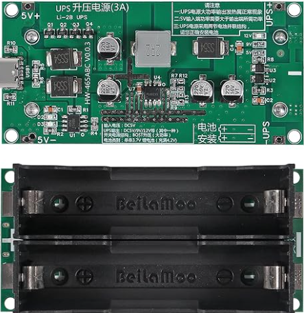
 Design with 5V UPS in Cirkit Designer
Introduction
A 5V Uninterruptible Power Supply (UPS) is a compact power management device designed to provide a stable 5V output to electronic devices during power outages or fluctuations. It ensures uninterrupted operation by seamlessly switching to a rechargeable battery when the primary power source fails. This makes it an essential component for critical systems, IoT devices, Raspberry Pi boards, and other low-power electronics that require reliable power delivery.
Explore Projects Built with 5V UPS
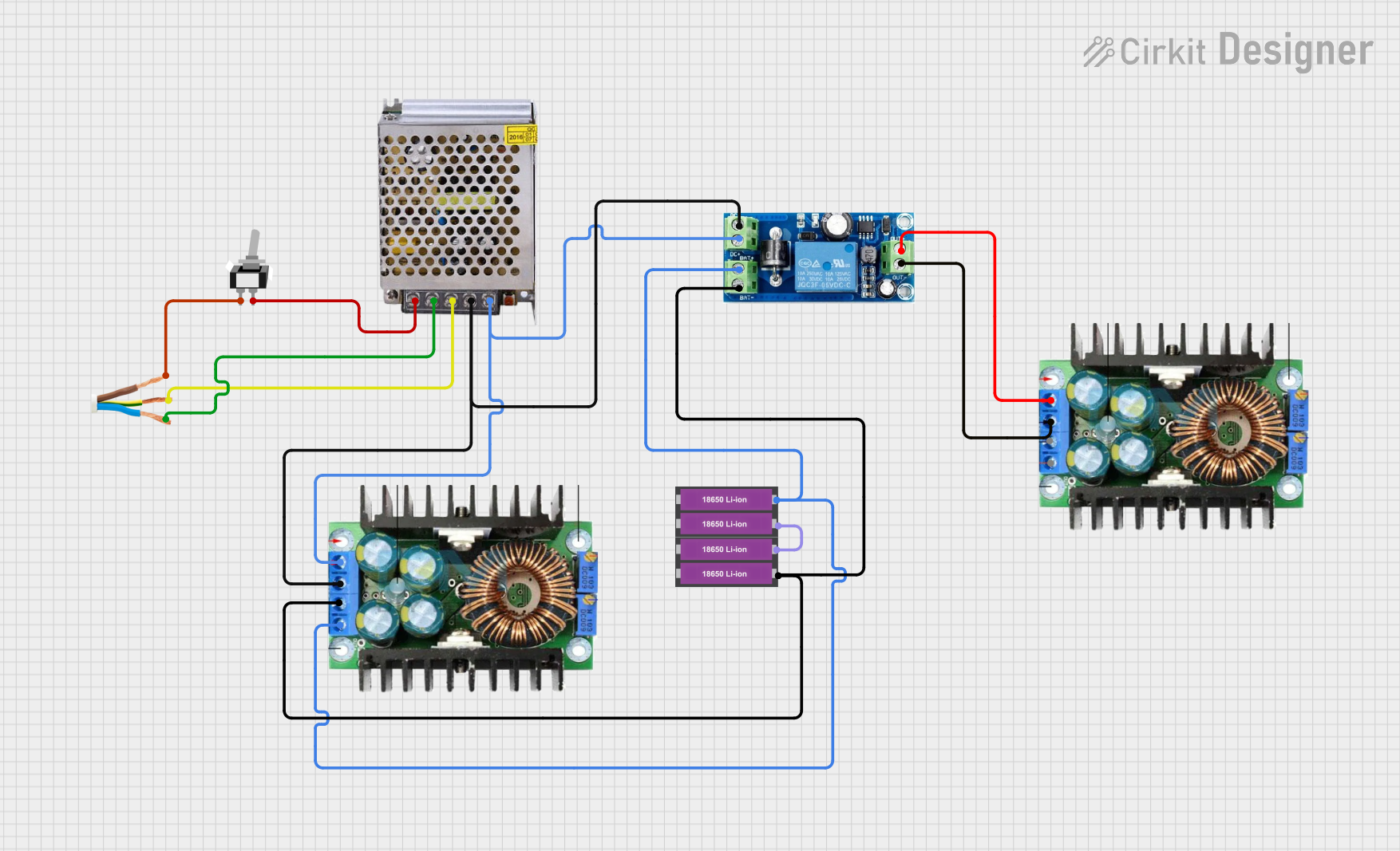 Open Project in Cirkit Designer
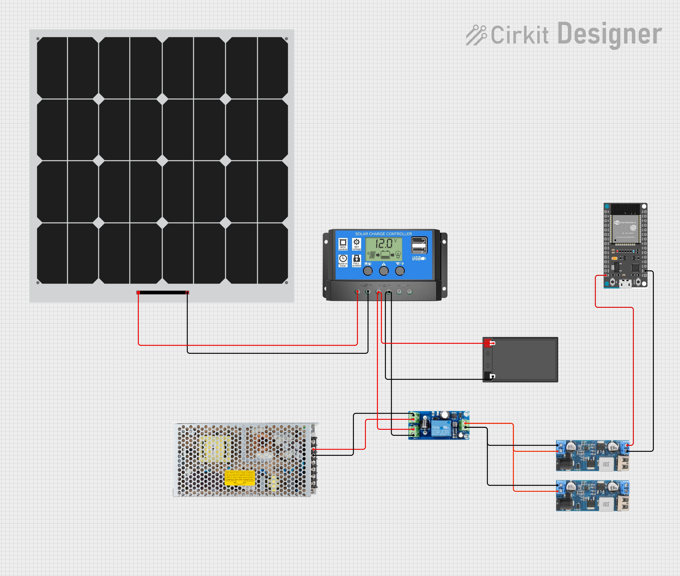 Open Project in Cirkit Designer
 Open Project in Cirkit Designer
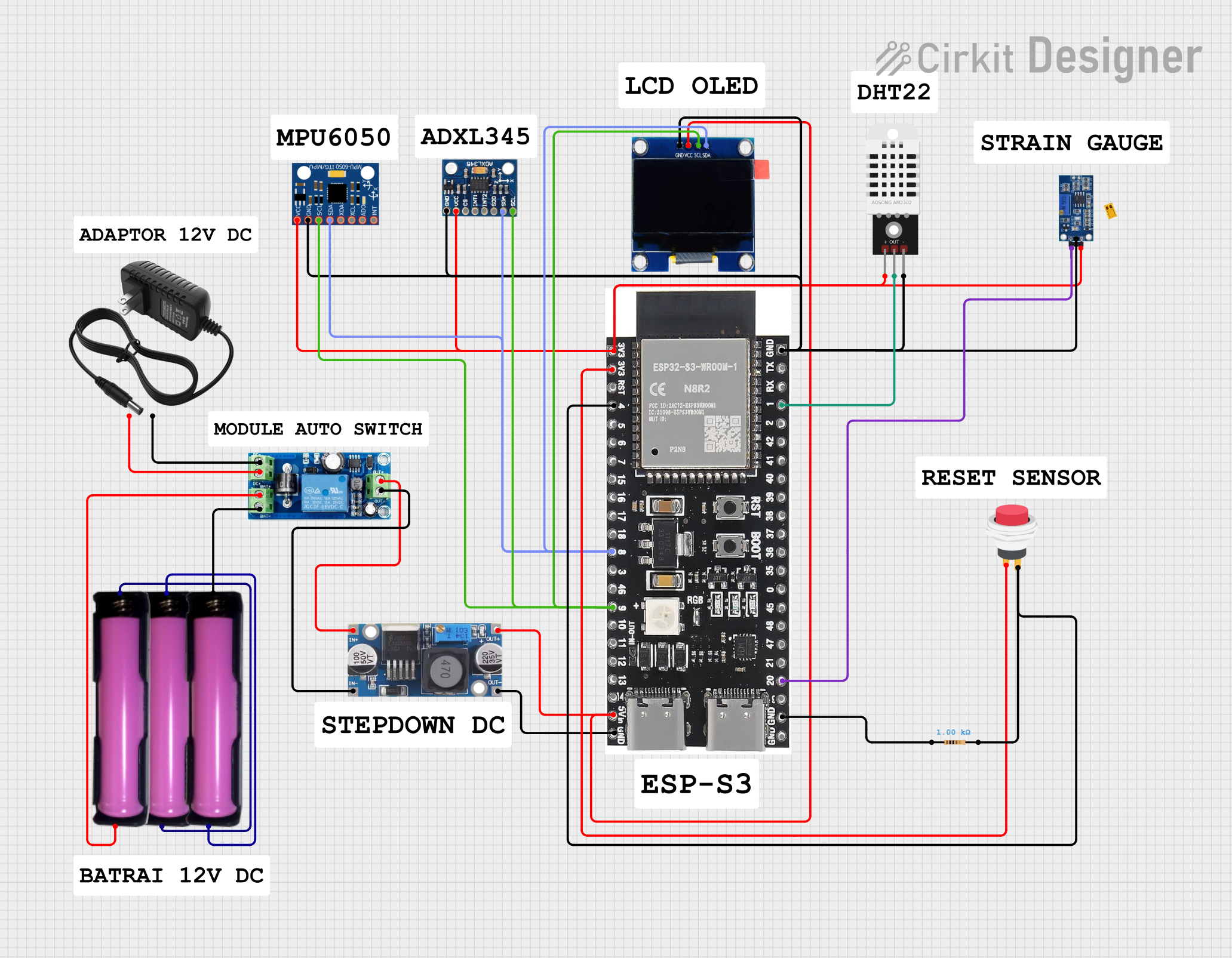 Open Project in Cirkit Designer
Explore Projects Built with 5V UPS
Open Project in Cirkit DesignerOpen Project in Cirkit DesignerOpen Project in Cirkit DesignerOpen Project in Cirkit DesignerCommon Applications and Use Cases
- Backup power for Raspberry Pi, Arduino, and other microcontroller-based systems.
- Ensuring uninterrupted operation of IoT devices in remote or critical environments.
- Powering routers, modems, or small network devices during outages.
- Providing stable power to sensors and data loggers in industrial or field applications.
Technical Specifications
The following table outlines the key technical details of the 5V UPS:
| Parameter | Value |
|---|---|
| Input Voltage Range | 5V DC ± 5% |
| Output Voltage | 5V DC ± 2% |
| Maximum Output Current | 2A |
| Battery Type | Lithium-ion or Lithium-polymer |
| Battery Capacity | Typically 2000mAh to 5000mAh |
| Charging Current | 1A (typical) |
| Switching Time | < 10ms |
| Operating Temperature | -10°C to 60°C |
| Dimensions | Varies by model (e.g., 60x40x20mm) |
Pin Configuration and Descriptions
The 5V UPS typically includes the following pins or connectors:
| Pin/Connector | Description |
|---|---|
| Input (Micro-USB/Type-C) | Connects to the primary 5V power source for charging the battery. |
| Output (USB-A/Pin Header) | Provides a stable 5V output to the connected device. |
| Battery Connector | Connects to the internal rechargeable battery (if removable). |
| Status Indicator LED | Indicates the charging and power status (e.g., red for charging, green for full). |
| Power Switch | Turns the UPS on or off (optional, depending on the model). |
Usage Instructions
How to Use the 5V UPS in a Circuit
- Connect the Input Power Source: Plug a 5V DC power adapter into the input port (e.g., Micro-USB or Type-C).
- Connect the Output Device: Attach the device requiring backup power to the output port (e.g., USB-A or pin header).
- Power On the UPS: If the UPS includes a power switch, ensure it is turned on.
- Monitor the Status LEDs: Check the LED indicators to confirm the UPS is charging and providing power correctly.
- Test Backup Functionality: Disconnect the input power source to verify that the UPS seamlessly switches to battery power.
Important Considerations and Best Practices
- Battery Selection: Use only the recommended battery type and capacity to ensure safe operation.
- Heat Management: Avoid placing the UPS in enclosed spaces without ventilation, as it may generate heat during operation.
- Load Limitations: Do not exceed the maximum output current (2A) to prevent damage to the UPS or connected devices.
- Regular Testing: Periodically test the UPS to ensure the battery is functioning correctly and can provide backup power.
- Firmware Updates: If the UPS includes a microcontroller, check for firmware updates from the manufacturer to improve performance.
Example: Using the 5V UPS with an Arduino UNO
The 5V UPS can be used to power an Arduino UNO during power outages. Connect the UPS output to the Arduino's 5V and GND pins. Below is an example Arduino sketch to monitor the UPS status using a digital input pin:
// Example code to monitor UPS status with Arduino UNO
const int upsStatusPin = 2; // Connect UPS status output to digital pin 2
const int ledPin = 13;      // Built-in LED to indicate UPS status

void setup() {
  pinMode(upsStatusPin, INPUT); // Set UPS status pin as input
  pinMode(ledPin, OUTPUT);      // Set LED pin as output
  Serial.begin(9600);           // Initialize serial communication
}

void loop() {
  int upsStatus = digitalRead(upsStatusPin); // Read UPS status pin

  if (upsStatus == HIGH) {
    // UPS is providing power
    digitalWrite(ledPin, HIGH); // Turn on LED
    Serial.println("UPS is active and providing power.");
  } else {
    // UPS is not active
    digitalWrite(ledPin, LOW); // Turn off LED
    Serial.println("UPS is not active.");
  }

  delay(1000); // Wait for 1 second before checking again
}
Note: Ensure the UPS has a status output pin that can be connected to the Arduino. If not, this code may not be applicable.
Troubleshooting and FAQs
Common Issues and Solutions
UPS Does Not Provide Backup Power
- Cause: The battery may be discharged or not connected properly.
- Solution: Check the battery connection and charge the UPS for at least 2 hours before use.
Device Restarts During Power Switch
- Cause: The switching time may be too long for sensitive devices.
- Solution: Use a capacitor across the output to stabilize the voltage during switching.
UPS Overheats
- Cause: Excessive load or poor ventilation.
- Solution: Reduce the load to within the specified limit and ensure proper airflow around the UPS.
LED Indicators Not Working
- Cause: Faulty LEDs or internal circuitry.
- Solution: Verify the input power and battery connection. If the issue persists, contact the manufacturer.
FAQs
Q: Can I use the 5V UPS with a Raspberry Pi?
A: Yes, the 5V UPS is compatible with Raspberry Pi boards. Ensure the output current meets the power requirements of your Raspberry Pi model.
Q: How long will the UPS provide backup power?
A: The backup duration depends on the battery capacity and the power consumption of the connected device. For example, a 2000mAh battery can power a 1A load for approximately 2 hours.
Q: Can I replace the battery in the UPS?
A: Some models allow battery replacement. Refer to the manufacturer's documentation to confirm compatibility and replacement procedures.
Q: Is the UPS safe to use with sensitive electronics?
A: Yes, the UPS is designed to provide stable power. However, ensure the load does not exceed the specified limits to avoid voltage drops.