
How to Use Pinoccio Scout r1.0: Examples, Pinouts, and Specs
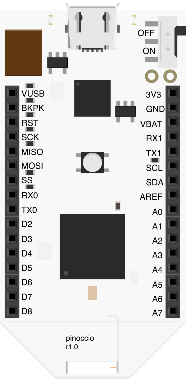
 Design with Pinoccio Scout r1.0 in Cirkit Designer
Introduction
The Pinoccio Scout r1.0 is a wireless microcontroller designed for Internet of Things (IoT) applications. Manufactured by Pinoccio, this versatile device features built-in Wi-Fi connectivity and an array of onboard sensors, making it ideal for environmental monitoring, data collection, and prototyping connected devices. Its compact design and robust feature set allow developers to quickly create and deploy IoT solutions.
Explore Projects Built with Pinoccio Scout r1.0
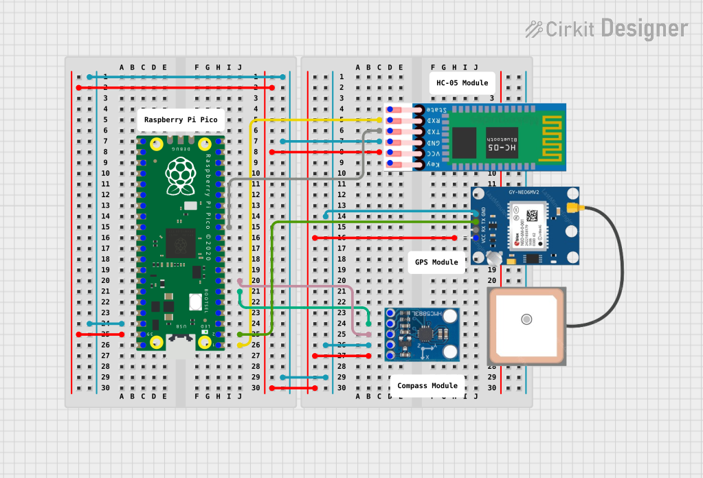 Open Project in Cirkit Designer
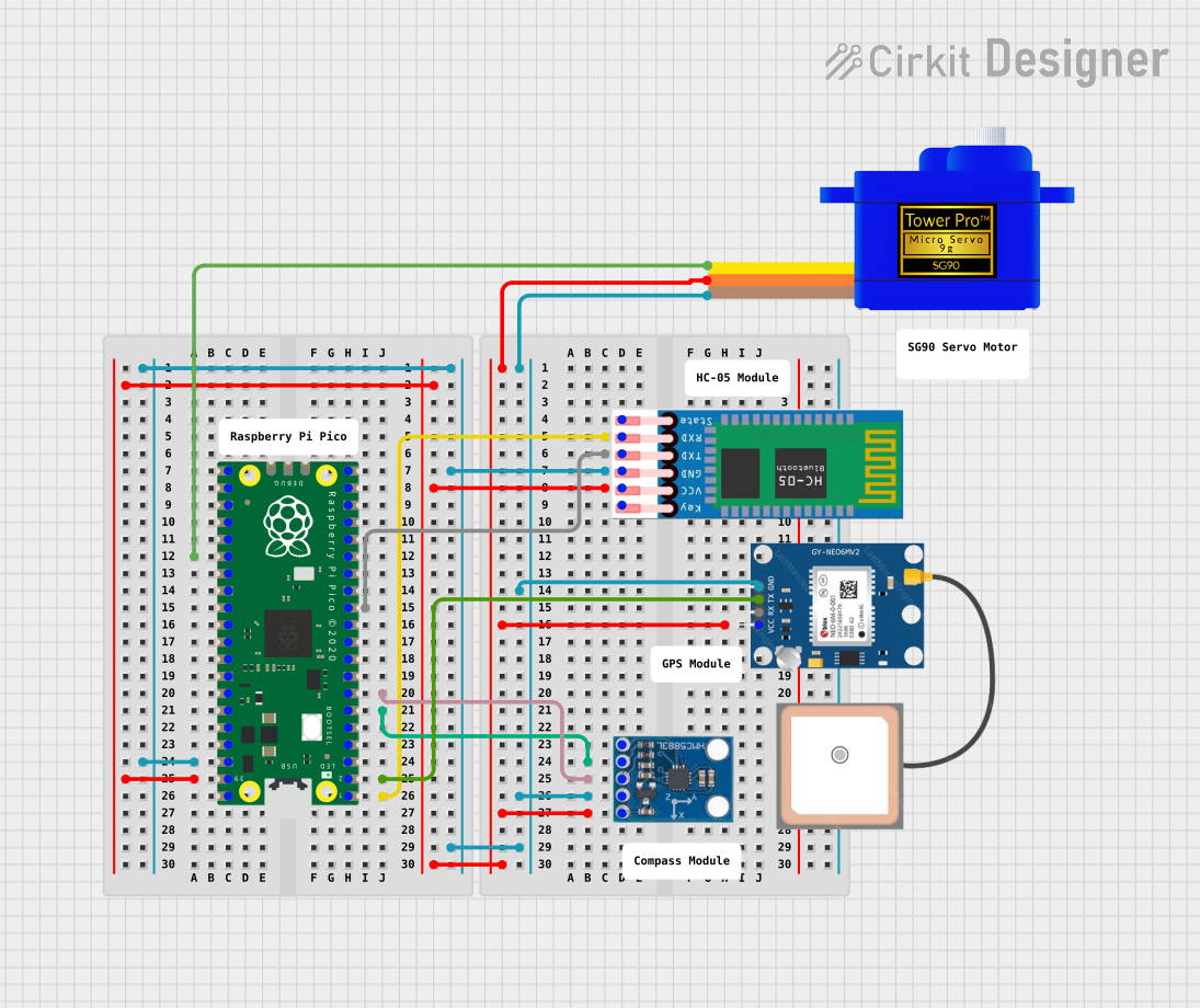 Open Project in Cirkit Designer
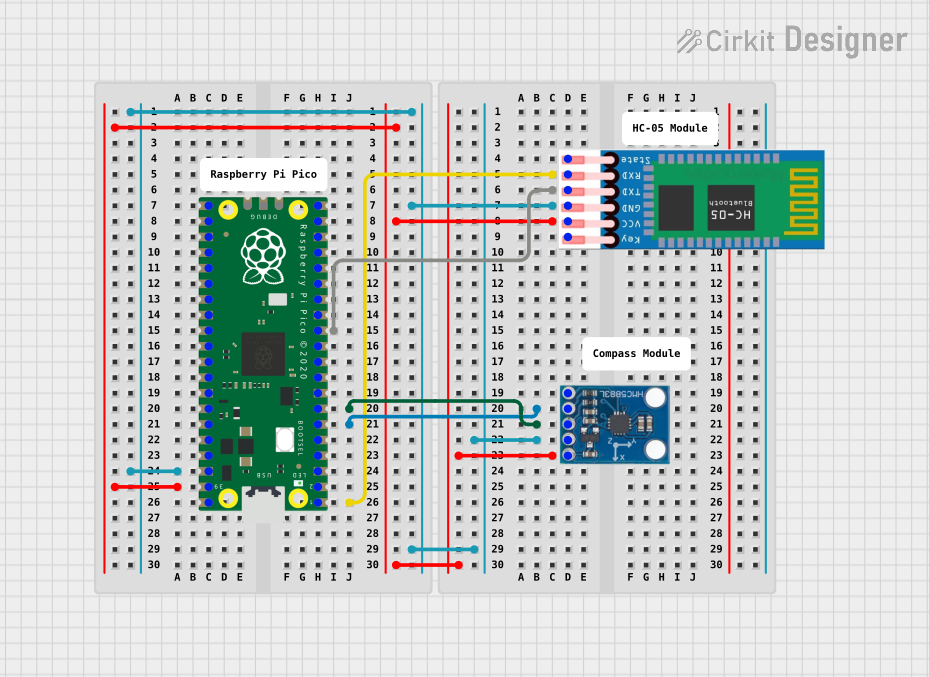 Open Project in Cirkit Designer
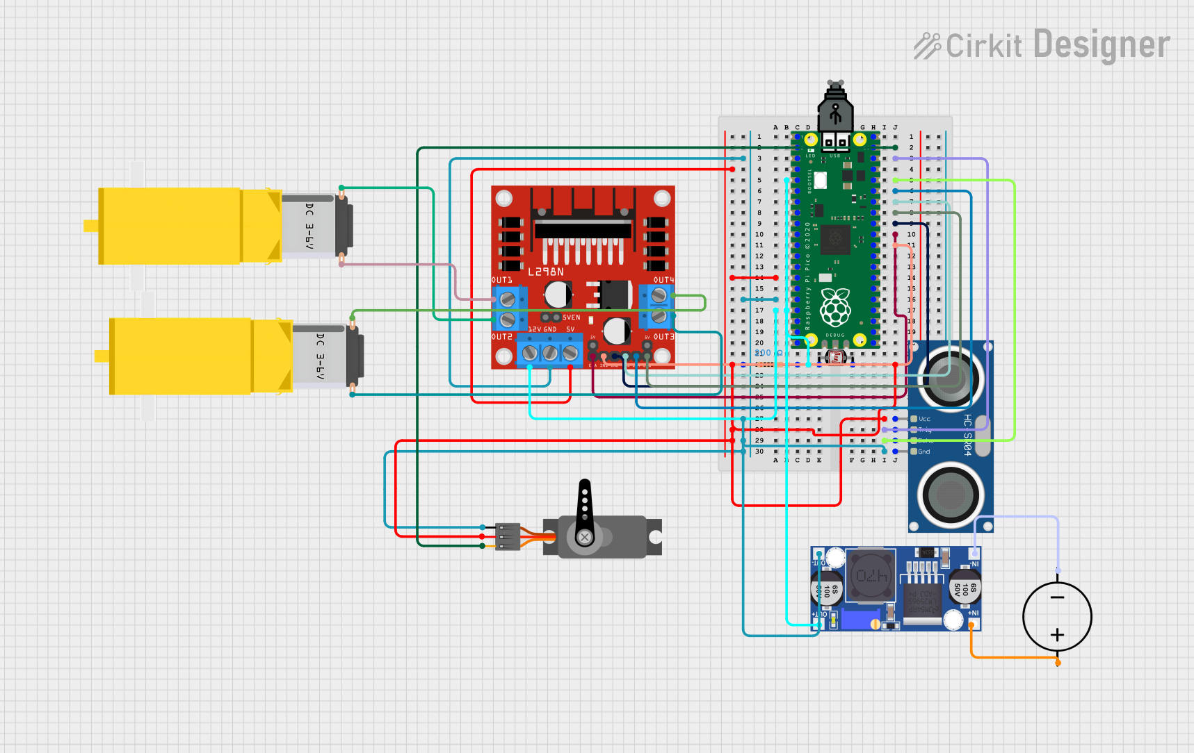 Open Project in Cirkit Designer
Explore Projects Built with Pinoccio Scout r1.0
Open Project in Cirkit DesignerOpen Project in Cirkit DesignerOpen Project in Cirkit DesignerOpen Project in Cirkit DesignerCommon Applications and Use Cases
- Smart home automation systems
- Environmental monitoring (e.g., temperature, humidity, light)
- Prototyping IoT devices
- Wireless sensor networks
- Data logging and remote monitoring
Technical Specifications
The following table outlines the key technical details of the Pinoccio Scout r1.0:
| Specification | Details |
|---|---|
| Microcontroller | ATmega128RFA1 (8-bit AVR with integrated 2.4GHz transceiver) |
| Operating Voltage | 3.3V |
| Input Voltage Range | 3.3V to 6V |
| Clock Speed | 16 MHz |
| Flash Memory | 128 KB |
| SRAM | 16 KB |
| EEPROM | 4 KB |
| Wireless Connectivity | IEEE 802.15.4 (2.4GHz) |
| Built-in Sensors | Temperature, light, battery voltage |
| Power Options | Rechargeable LiPo battery (via JST connector) or USB power |
| USB Interface | Micro-USB |
| Dimensions | 2.0 x 1.0 inches |
Pin Configuration and Descriptions
The Pinoccio Scout r1.0 features a variety of pins for interfacing with external components. Below is the pin configuration:
| Pin | Type | Description |
|---|---|---|
| VCC | Power | 3.3V power supply output |
| GND | Ground | Ground connection |
| D0-D13 | Digital I/O | General-purpose digital input/output pins |
| A0-A7 | Analog Input | Analog input pins (10-bit resolution) |
| SDA | I2C Data | Data line for I2C communication |
| SCL | I2C Clock | Clock line for I2C communication |
| TX | UART Transmit | Transmit pin for serial communication |
| RX | UART Receive | Receive pin for serial communication |
| RESET | Reset | Resets the microcontroller |
| BAT | Battery Input | Connects to the LiPo battery for power |
Usage Instructions
How to Use the Pinoccio Scout r1.0 in a Circuit
Powering the Device:
- Connect a 3.7V LiPo battery to the JST connector, or power the device via the Micro-USB port.
- Ensure the input voltage does not exceed 6V to avoid damaging the device.
Programming the Microcontroller:
- Use the Arduino IDE to program the Scout r1.0. Select "Pinoccio Scout" as the board in the IDE.
- Connect the Scout to your computer using a Micro-USB cable.
Connecting Sensors and Actuators:
- Use the digital I/O pins (D0-D13) for connecting LEDs, relays, or other digital devices.
- Use the analog input pins (A0-A7) for reading sensor data such as temperature or light levels.
Wireless Communication:
- The Scout r1.0 supports IEEE 802.15.4 for wireless communication. Use the built-in transceiver to create a wireless mesh network or communicate with other Scouts.
Important Considerations and Best Practices
- Power Management: Use a fully charged LiPo battery for optimal performance. Monitor the battery voltage using the built-in sensor to avoid over-discharging.
- Heat Dissipation: Avoid placing the device in enclosed spaces without ventilation, as prolonged operation may generate heat.
- Firmware Updates: Regularly update the firmware to ensure compatibility with the latest features and bug fixes.
Example Code for Arduino IDE
Below is an example code snippet to read the onboard temperature sensor and send the data over serial communication:
// Pinoccio Scout r1.0 - Temperature Sensor Example
// This code reads the onboard temperature sensor and prints the value to the Serial Monitor.

void setup() {
  Serial.begin(9600); // Initialize serial communication at 9600 baud
  pinMode(A0, INPUT); // Configure A0 as an input for the temperature sensor
}

void loop() {
  int sensorValue = analogRead(A0); // Read the analog value from the temperature sensor
  float voltage = sensorValue * (3.3 / 1023.0); // Convert the analog value to voltage
  float temperature = (voltage - 0.5) * 100.0; // Convert voltage to temperature in Celsius

  Serial.print("Temperature: ");
  Serial.print(temperature);
  Serial.println(" °C"); // Print the temperature value to the Serial Monitor

  delay(1000); // Wait for 1 second before reading again
}
Troubleshooting and FAQs
Common Issues and Solutions
Device Not Powering On:
- Ensure the battery is properly connected and charged.
- Verify the USB cable is functional and securely connected.
Unable to Upload Code:
- Check that the correct board ("Pinoccio Scout") is selected in the Arduino IDE.
- Ensure the correct COM port is selected.
- Press the RESET button before uploading if the device is unresponsive.
Wireless Communication Fails:
- Verify that the Scout is within range of other devices in the network.
- Check for interference from other 2.4GHz devices.
Inaccurate Sensor Readings:
- Calibrate the sensors if necessary.
- Ensure the device is not exposed to extreme environmental conditions.
FAQs
Q: Can I use the Scout r1.0 without a battery?
A: Yes, the device can be powered directly via the Micro-USB port.
Q: What is the range of the wireless transceiver?
A: The range depends on environmental factors but typically extends up to 30 meters indoors and 100 meters outdoors.
Q: Is the Scout r1.0 compatible with Arduino libraries?
A: Yes, the Scout r1.0 is compatible with most Arduino libraries, making it easy to integrate with existing projects.
Q: How do I update the firmware?
A: Firmware updates can be performed via the Arduino IDE or the Pinoccio web interface. Follow the manufacturer's instructions for detailed steps.